Lexus ES: System Diagram
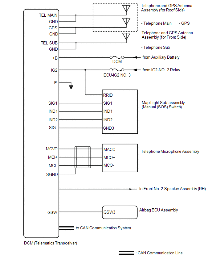
SYSTEM DIAGRAM
READ NEXT:
 Terminals Of Ecu
TERMINALS OF ECU Terminal No. (Symbol) Wiring Color Terminal Description Condition Specified Condition G128-1 (+B) - G128-20 (E) BR - W-B Power source (+B) Power switch off 11
Unable To Connect To Call Center
DESCRIPTION This may occur when the intensity of telephone radio frequency was very weak, or the safety connect system has a malfunction and a DTC is set. PROCEDURE 1. CHECK COMMUNICATION SERVIC
Vehicle Control History
VEHICLE CONTROL HISTORY NOTICE: Make sure to record any output Vehicle Control History codes before clearing them and checking the Vehicle Control History again. CHECK VEHICLE CONTROL HISTORY NOTICE:
SEE MORE:
Parts Location
PARTS LOCATION ILLUSTRATION *1 FRONT TELEVISION CAMERA ASSEMBLY *2 BRAKE ACTUATOR ASSEMBLY - SKID CONTROL ECU *3 SIDE TELEVISION CAMERA ASSEMBLY RH *4 SIDE TELEVISION CAMERA ASSEMBLY LH *5 ECM *6 PARK/NEUTRAL POSITION SWITCH ASSEMBLY *7 REAR TELEVISION CAMERA ASSE
Freeze Frame Data
FREEZE FRAME DATA FREEZE FRAME DATA HINT: The hybrid vehicle control ECU records vehicle and driving condition information as freeze frame data the moment a DTC is stored. It can be used for estimating or duplicating the vehicle conditions that were present when the malfunction occurred. (a) Connect
© 2016-2026 Copyright www.lexguide.net
