Lexus ES: Removal
REMOVAL
CAUTION / NOTICE / HINT
The necessary procedures (adjustment, calibration, initialization or registration) that must be performed after parts are removed and installed, or replaced during service plug grip removal/installation are shown below.
Necessary Procedures After Parts Removed/Installed/Replaced| Replaced Part or Performed Procedure | Necessary Procedure | Effect/Inoperative Function when Necessary Procedure not Performed | Link |
|---|---|---|---|
|
*: When performing learning using the Techstream.
Click here | |||
| Auxiliary battery terminal is disconnected/reconnected | Perform steering sensor zero point calibration | Lane Control System | |
| Pre-collision System | |||
| Parking Support Brake System* | |||
| Lighting System | |||
| Memorize steering angle neutral point | Parking assist monitor system | | |
| Panoramic view monitor system | | ||
| Initialize power trunk lid system | Power Trunk Lid System | | |
CAUTION:
-
Orange wire harnesses and connectors indicate high-voltage circuits. To prevent electric shock, always follow the procedure described in the repair manual.
.png)
Click here
.gif)
-
To prevent electric shock, wear insulated gloves when working on wire harnesses and components of the high voltage system.
.png)
NOTICE:
- After the power switch is turned off, the radio receiver assembly records various types of memory and settings. As a result, after turning the power switch off, make sure to wait at least 85 seconds before disconnecting the cable from the negative (-) auxiliary battery terminal. (for Audio and Visual System)
- After the power switch is turned off, the radio receiver assembly records various types of memory and settings. As a result, after turning the power switch off, make sure to wait at least 85 seconds before disconnecting the cable from the negative (-) auxiliary battery terminal. (for Navigation System)
PROCEDURE
1. CHECK FOR DTC
(a) Check for DTCs.
Click here
CAUTION:
-
Confirm that DTC P0AA649 (Hybrid / EV Battery Voltage System Isolation Internal Electronic Failure), P1C7C49 (Hybrid / EV Battery Voltage System Isolation (A/C Area) Internal Electronic Failure), P1C7D49 (Hybrid / EV Battery Voltage System Isolation (Hybrid/EV Battery Area) Internal Electronic Failure), P1C7E49 (Hybrid / EV Battery Voltage System Isolation (Transaxle Area) Internal Electronic Failure) or P1C7F49 (Hybrid / EV Battery Voltage System Isolation (Direct Current Area) Internal Electronic Failure) is not output before removing or installing the HV battery. If this DTC is output, perform troubleshooting for this DTC first.
- To reduce the risk of electric shock, do not perform troubleshooting before checking for DTCs.
2. DISCONNECT CABLE FROM NEGATIVE AUXILIARY BATTERY TERMINAL
Click here
3. REMOVE BATTERY SERVICE HOLE COVER
Click here
4. REMOVE SERVICE PLUG GRIP
CAUTION:
- Be sure to wear insulated gloves.
-
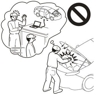
Do not inspect or service the high voltage system with the service plug grip installed.
.png)
- To reduce the risk of electric shock, make sure to remove the service plug grip to cut off the high voltage circuit before servicing the vehicle.
-
To reduce the risk of electric shock, make sure to wait at least 10 minutes after removing the service plug grip to fully discharge the high voltage capacitor inside the inverter with converter assembly.
.png)
- Keep the removed service plug grip in your pocket to prevent other technicians from accidentally installing it while you are servicing the vehicle.
NOTICE:
- After removing the service plug grip, turning the power switch on (READY) may cause a malfunction. Do not turn the power switch on (READY) unless instructed by the repair manual.
- Do not touch the terminals of the service plug grip.
- If the service plug grip has been struck or dropped, replace it.
HINT:
Waiting for at least 10 minutes is required to discharge the high voltage capacitor inside the inverter with converter assembly.
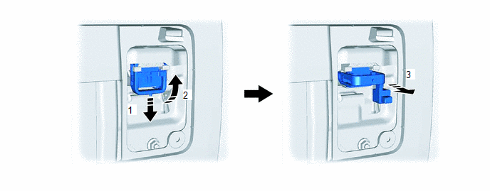
(a) While wearing insulated gloves, rotate the handle of the service plug grip and remove the service plug grip as indicated by the arrows, in the order shown in the illustration.
READ NEXT:
 Inspection
INSPECTION PROCEDURE 1. INSPECT SERVICE PLUG GRIP (a) Measure the resistance according to the value(s) in the table below. Standard Resistance: Tester Connection Condition Specified Conditi
Installation
INSTALLATION PROCEDURE 1. INSTALL SERVICE PLUG GRIP CAUTION: Be sure to wear insulated gloves. NOTICE: Before installing the service plug grip, check that no parts or tools remain and that the high vo
Sub Radiator
ComponentsCOMPONENTS ILLUSTRATION *1 RADIATOR ASSEMBLY - - RemovalREMOVAL CAUTION / NOTICE / HINT The necessary procedures (adjustment, calibration, initialization or registration) that
SEE MORE:
PCU Interlock Circuit Open (P1CE213,P1CE292)
DTC SUMMARY MALFUNCTION DESCRIPTION The hybrid vehicle control ECU detects that a safety device (interlock) is operated or that there is an open circuit in the detection circuit. (Even if an open circuit occurs while the vehicle is stopped, the system determines that the safety device was operated.)
Wiper and Washer Switch Circuit
DESCRIPTION The condition of the windshield wiper switch assembly is detected and sent to the steering sensor in this circuit. WIRING DIAGRAM PROCEDURE 1. READ VALUE USING TECHSTREAM (a) Connect the Techstream to the DLC3. (b) Turn the engine switch on (IG). (c) Turn the Techstream on. (d)
