Lexus ES: On-vehicle Inspection
ON-VEHICLE INSPECTION
PROCEDURE
1. INSPECT RAIN SENSOR
| (a) Disconnect the rain sensor connector. |
|
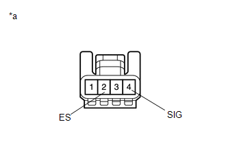
(b) Measure the voltage according to the value(s) in the table below.
Standard Voltage:
| Tester Connection | Condition | Specified Condition |
|---|---|---|
| 4 (SIG) - 2 (ES) | Engine switch on (IG) | 11 to 14 V |
(c) Measure the resistance according to the value(s) in the table below.
Standard Resistance:
| Tester Connection | Condition | Specified Condition |
|---|---|---|
| 2 (ES) - Body ground | Always | Below 1 Ω |
HINT:
If the result is not as specified, replace the rain sensor.
| (d) Reconnect the rain sensor connector. |
|
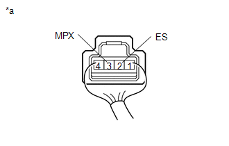
(e) Connect an oscilloscope to terminal 3 (MPX) and 2 (ES) of the rain sensor connector.
(f) Check for pulses according to the value(s) in the table below.
OK:
| Tester Connection | Condition | Specified Condition |
|---|---|---|
| 3 (MPX) - 2 (ES) | Engine switch on (IG) Front wiper switch in auto | Pulse generation |
HINT:
If the result is not as specified, replace the rain sensor.
READ NEXT:
 Removal
REMOVAL PROCEDURE 1. REMOVE RAIN SENSOR COVER *a Stopper Remove in this Direction (1) Remove in this Direction (2) (a) Release the stopper by pulling it out and disconnect the r
Installation
INSTALLATION PROCEDURE 1. INSTALL RAIN SENSOR TAPE HINT: The rain sensor tape is reusable. Only replace the tape if it is damaged or contaminated with foreign matter. (a) Clean the sensing portion of
Relay
On-vehicle InspectionON-VEHICLE INSPECTION PROCEDURE 1. INSPECT WIPER RELAY (a) Measure the resistance according to the value(s) in the table below. Standard Resistance: Tester Connection Co
SEE MORE:
Luggage Compartment Door Closer does not Operate
DESCRIPTION The luggage compartment door closer operation controls the luggage door closer assembly via the luggage closer motor assembly based on switch signals in the luggage door closer assembly. WIRING DIAGRAM CAUTION / NOTICE / HINT NOTICE:
Check that B2250 or B2251 is not output before pro
Fail-safe Chart
FAIL-SAFE CHART FAIL-SAFE FUNCTION (a) If a malfunction is detected in the parking support brake system, the warning message "Parking Support Brake Malfunction Visit Your Dealer", "Parking Support Brake Unavailable" or "Parking Support Brake Unavailable Remove the Dirt of Rear Camera", is displayed
