Lexus ES: Removal
REMOVAL
CAUTION / NOTICE / HINT
The necessary procedures (adjustment, calibration, initialization, or registration) that must be performed after parts are removed, installed, or replaced during the steering wheel switch housing removal/installation are shown below.
Necessary Procedure After Parts Removed/Installed/Replaced (for HV Model)| Replaced Part or Performed Procedure | Necessary Procedure | Effect/Inoperative Function When Necessary Procedures are not Performed | Link |
|---|---|---|---|
|
*: When performing learning using the Techstream.
Click here | |||
| Disconnect cable from negative auxiliary battery terminal | Perform steering sensor zero point calibration | Lane Control System (for HV Model) | |
| Pre-collision System (for HV Model) | |||
| Parking Support Brake System (for HV Model)* | |||
| Lighting System (for HV Model) | |||
| Memorize steering angle neutral point | Parking Assist Monitor System (for HV Model) | | |
| Panoramic View Monitor System (for HV Model) | | ||
| Initialize power trunk lid system | Power Trunk Lid System (for HV Model) | | |
| Removal/installation of the spiral cable with sensor sub-assembly | Steering angle zero point learning (Initialize parking support brake system) |
| |
| Parking Assist Monitor System (for HV Model) | for Initialization for Calibration | |
| Steering angle zero point learning (Initialize panoramic view monitor system) | Panoramic View Monitor System (for HV Model) | for Initialization for Calibration | |
CAUTION:
Some of these service operations affect the SRS airbag system. Read the precautionary notices concerning the SRS airbag system before servicing.
.png)
Click here .gif)
NOTICE:
- After the power switch is turned off, the radio receiver assembly records various types of memory and settings. As a result, after turning the power switch off, make sure to wait at least 85 seconds before disconnecting the cable from the negative (-) auxiliary battery terminal. (for Audio and Visual System)
- After the power switch is turned off, the radio receiver assembly records various types of memory and settings. As a result, after turning the power switch off, make sure to wait at least 85 seconds before disconnecting the cable from the negative (-) auxiliary battery terminal. (for Navigation System)
| Replaced Part or Performed Procedure | Necessary Procedure | Effect/Inoperative Function when Necessary Procedure not Performed | Link |
|---|---|---|---|
|
*: When performing learning using the Techstream.
Click here | |||
| Disconnect cable from negative battery terminal | Perform steering sensor zero point calibration | Lane Control System (for Gasoline Model) | |
| Pre-collision System (for Gasoline Model) | |||
| Parking Support Brake System (for Gasoline Model)* | |||
| Lighting System (for Gasoline Model) | |||
| Memorize steering angle neutral point | Parking Assist Monitor System (for Gasoline Model) | | |
| Panoramic View Monitor System (for Gasoline Model) | | ||
| Initialize power trunk lid system | Power Trunk Lid System (for Gasoline Model) | | |
| Removal/installation of the spiral cable with sensor sub-assembly | Steering angle zero point learning (Initialize parking support brake system) |
| |
| Parking Assist Monitor System (for Gasoline Model) | for Initialization for Calibration | |
| Steering angle zero point learning (Initialize panoramic view monitor system) | Panoramic View Monitor System (for Gasoline Model) | for Initialization for Calibration | |
CAUTION:
Some of these service operations affect the SRS airbag system. Read the precautionary notices concerning the SRS airbag system before servicing.
Click here
NOTICE:
- After the engine switch is turned off, the radio receiver assembly records various types of memory and settings. As a result, after turning the engine switch off, make sure to wait at least 85 seconds before disconnecting the cable from the negative (-) battery terminal. (for Audio and Visual System)
- After the engine switch is turned off, the radio receiver assembly records various types of memory and settings. As a result, after turning the engine switch off, make sure to wait at least 85 seconds before disconnecting the cable from the negative (-) battery terminal. (for Navigation System)
PROCEDURE
1. REMOVE SPIRAL CABLE WITH SENSOR SUB-ASSEMBLY
Click here
2. REMOVE TILT AND TELESCOPIC SWITCH (for Power Tilt and Power Telescopic Steering Column)
Click here
3. REMOVE WINDSHIELD WIPER SWITCH ASSEMBLY
Click here
4. REMOVE TURN SIGNAL SWITCH
Click here
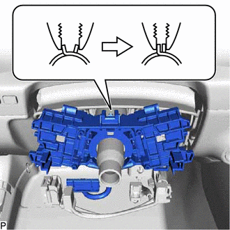
5. REMOVE STEERING WHEEL SWITCH HOUSING
| (a) Using pliers, expand the clamp as shown in the illustration. |
|
(b) While holding the clamp expanded, using a screwdriver with its tip wrapped with protective tape, disengage the claw and remove the steering wheel switch housing as shown in the illustration.
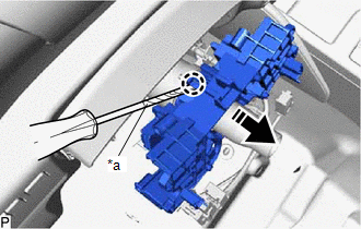
| *a | Protective Tape |
.png) | Remove in this Direction |
READ NEXT:
 Inspection
INSPECTION PROCEDURE 1. INSPECT STEERING WHEEL SWITCH HOUSING *a Component without harness connected (Steering Wheel Switch Housing) - - (a) Measure the resistance according to the value(
Installation
INSTALLATION PROCEDURE 1. INSTALL STEERING WHEEL SWITCH HOUSING (a) When reusing the steering wheel switch housing: (1) Using pliers, expand the clamp and temporarily install the steering wheel swi
SEE MORE:
Taillight Relay Circuit
DESCRIPTION The main body ECU (multiplex network body ECU) controls the operation of the TAIL relay. WIRING DIAGRAM CAUTION / NOTICE / HINT NOTICE:
Inspect the fuses for circuits related to this system before performing the following procedure.
Before replacing the main body ECU (multiplex net
Components
COMPONENTS ILLUSTRATION *1 CAM TIMING OIL CONTROL SOLENOID ASSEMBLY *2 NO. 1 ENGINE COVER SUB-ASSEMBLY *3 O-RING - - N*m (kgf*cm, ft.*lbf): Specified torque ● Non-reusable part ★ Precoated part - -
