Lexus ES: Inspection
INSPECTION
PROCEDURE
1. INSPECT STEERING WHEEL SWITCH HOUSING
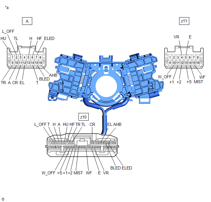
| *a | Component without harness connected (Steering Wheel Switch Housing) | - | - |
(a) Measure the resistance according to the value(s) in the table below.
Standard Resistance:
Light Switch Circuit| Tester Connection | Condition | Specified Condition |
|---|---|---|
| A-2 (L_OFF) - z10-2 (L_OFF) | Always | Below 1 Ω |
| A-14 (T) - z10-3 (T) | Always | Below 1 Ω |
| A-5 (H) - z10-4 (H) | Always | Below 1 Ω |
| A-10 (A) - z10-5 (A) | Always | Below 1 Ω |
| A-1 (HU) - z10-6 (HU) | Always | Below 1 Ω |
| A-6 (HF) - z10-7 (HF) | Always | Below 1 Ω |
| A-9 (TR) - z10-8 (TR) | Always | Below 1 Ω |
| A-3 (TL) - z10-9 (TL) | Always | Below 1 Ω |
| A-11 (CR) - z10-10 (CR) | Always | Below 1 Ω |
| A-12 (EL) - z10-13 (EL) | Always | Below 1 Ω |
| A-16 (AHB) - z10-14 (AHB) | Always | Below 1 Ω |
| A-15 (BLED) - z10-15 (BLED) | Always | Below 1 Ω |
| A-7 (ELED) - z10-16 (ELED) | Always | Below 1 Ω |
| Tester Connection | Condition | Specified Condition |
|---|---|---|
| z11-10 (W_OFF) - z10-24 (W_OFF) | Always | Below 1 Ω |
| z11-13 (+S) - z10-25 (+S) | Always | Below 1 Ω |
| z11-11 (+1) - z10-26 (+1) | Always | Below 1 Ω |
| z11-12 (+2) - z10-27 (+2) | Always | Below 1 Ω |
| z11-14 (MIST) - z10-28 (MIST) | Always | Below 1 Ω |
| z11-15 (WF) - z10-31 (WF) | Always | Below 1 Ω |
| z11-5 (E) - z10-33 (E) | Always | Below 1 Ω |
| z11-4 (VR) - z10-34 (VR) | Always | Below 1 Ω |
If the result is not as specified, replace the steering wheel switch housing.
READ NEXT:
 Installation
INSTALLATION PROCEDURE 1. INSTALL STEERING WHEEL SWITCH HOUSING (a) When reusing the steering wheel switch housing: (1) Using pliers, expand the clamp and temporarily install the steering wheel swi
SEE MORE:
Installation
INSTALLATION PROCEDURE 1. TEMPORARILY INSTALL FUEL PUMP ASSEMBLY (a) Turn the crankshaft pulley until the flat of the camshaft faces the fuel pump lifter assembly. HINT: This prevents the camshaft nose from pushing up the fuel pump lifter assembly when installing the fuel pump assembly.
Diagnostic Trouble Code Chart
DIAGNOSTIC TROUBLE CODE CHART Power Tilt and Power Telescopic Steering Column System DTC No. Detection Item DTC Detection Condition Link B26031C Tilt and Telescopic Manual Switch Circuit Circuit Voltage Out of Range When operating the tilt and telescopic switch, an abnormal voltage
