Lexus ES: On-vehicle Inspection
ON-VEHICLE INSPECTION
PROCEDURE
1. CHECK FUEL PUMP WITH FILTER ASSEMBLY OPERATION AND INSPECT FOR FUEL LEAK
(a) Check fuel pump operation.
(1) Connect the Techstream to the DLC3.
(2) Turn the engine switch on (IG).
NOTICE:
Do not start the engine.
(3) Turn the Techstream on.
(4) Enter the following menus: Powertrain / Engine / Active Test / Activate the Circuit Relay.
Powertrain > Engine > Active Test| Tester Display |
|---|
| Activate the Circuit Relay |
(5) Check for pressure in the fuel tube sub-assembly from the fuel line. Check that sounds of fuel flowing from the fuel tank assembly can be heard. If no sounds can be heard, check the relay, fuel pump with filter assembly, ECM and wiring connectors.
(b) Inspect for fuel leaks.
(1) Check that there are no fuel leaks from the fuel system after doing any maintenance or repairs. If there is a fuel leak, repair or replace parts as necessary.
(c) Turn the engine switch off.
(d) Disconnect the Techstream from the DLC3.
2. CHECK FUEL PRESSURE
(a) Discharge fuel system pressure.
Click here .gif)
(b) Measure the battery voltage.
Standard Voltage:
11 to 14 V
| (c) Disengage the 2 claws to remove the No. 2 fuel pipe clamp. |
|
.png)
| (d) Remove the fuel pipe clamp from the fuel tube connector. |
|
.png)
| (e) Disconnect the No. 2 fuel tube sub-assembly (for Direct Injection). (1) Disconnect the No. 2 fuel tube sub-assembly from the fuel pipe. Click here |
|
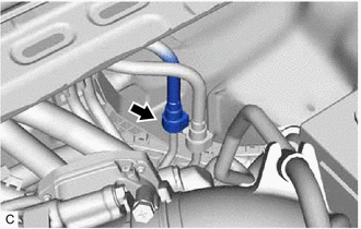
| (f) Disconnect the fuel tube sub-assembly (for Port Injection). (1) Disconnect the fuel tube sub-assembly from the fuel pipe. Click here |
|
.png)
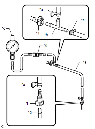
| (g) Install SST (EFI fuel pressure gauge) as shown in the illustration. SST: 09268-45101 09268-41250 09268-41260 09268-41280 09268-41500 09268-41700 95336-08070 |
|
(h) Wipe up any spilled fuel.
(i) Connect the cable to the negative (-) battery terminal.
NOTICE:
When disconnecting the cable, some systems need to be initialized after the cable is reconnected.
Click here
(j) Connect the Techstream to the DLC3.
(k) Turn the engine switch on (IG).
NOTICE:
Do not start the engine.
(l) Turn the Techstream on.
(m) Enter the following menus: Powertrain / Engine / Active Test / Activate the Circuit Relay.
Powertrain > Engine > Active Test| Tester Display |
|---|
| Activate the Circuit Relay |
(n) Measure the fuel pressure.
Standard Fuel Pressure:
196 to 833 kPa (2.0 to 8.5 kgf/cm2, 28 to 121 psi)
- If the fuel pressure is more than the standard, replace the fuel main valve assembly.
- If the fuel pressure is less than the standard, check the fuel hoses and their connections, fuel pump with filter assembly, fuel filter (fuel suction plate sub-assembly) and fuel main valve assembly.
(o) Disconnect the Techstream from the DLC3.
(p) Start the engine.
(q) Measure the fuel pressure at idle.
Standard Fuel Pressure:
196 to 833 kPa (2.0 to 8.5 kgf/cm2, 28 to 121 psi)
HINT:
Refer to Standard Idle Speed.
Click here
(r) Stop the engine.
(s) Check that the fuel pressure remains as specified for 5 minutes.
Standard Fuel Pressure:
98 kPa (1.0 kgf/cm2, 14.2 psi) or more
If the result is not as specified, check the fuel pump with filter assembly, fuel main valve assembly and/or fuel injector assemblies.
(t) After checking the fuel pressure, disconnect the cable from the negative (-) battery terminal and carefully remove SST to prevent fuel from spraying.
NOTICE:
When disconnecting the cable, some systems need to be initialized after the cable is reconnected.
Click here
(u) Connect the fuel tube sub-assembly (for Port Injection).
(1) Connect the fuel tube sub-assembly to the fuel pipe.
Click here
(v) Connect the No. 2 fuel tube sub-assembly (for Direct Injection).
(1) Connect the No. 2 fuel tube sub-assembly to the fuel pipe.
Click here
(w) Install the fuel pipe clamp to the fuel tube connector.
(x) Engage the 2 claws to install the No. 2 fuel pipe clamp.
(y) Connect the cable to the negative (-) battery terminal.
NOTICE:
When disconnecting the cable, some systems need to be initialized after the cable is reconnected.
Click here
(z) Inspect for fuel leaks.
Click here
3. CHECK FUEL PRESSURE (for High Pressure)
(a) Connect the Techstream to the DLC3.
(b) Turn the engine switch on (IG).
(c) Turn the Techstream on.
(d) Enter the following menus: Powertrain / Engine / Data List / Engine Speed, Coolant Temperature, Fuel Pressure (High) and Injection Mode.
Powertrain > Engine > Data List| Tester Display |
|---|
| Engine Speed |
| Coolant Temperature |
| Fuel Pressure (High) |
| Injection Mode |
(e) Start the engine and warm it up until the engine coolant temperature is 75°C (167°F) or higher with all the accessories switched off.
(f) According to the display on the Techstream, read the Data List.
Standard:
| Techstream Display | Condition | Specified Condition |
|---|---|---|
| Fuel Pressure (High) |
| 2400 to 20000 kPag |
If the result is not as specified, check the fuel pump with filter assembly (for Low Pressure), fuel pump assembly (for High Pressure), fuel pressure sensor (fuel delivery pipe with sensor assembly LH) (for High Pressure) and wire harnesses.
(g) Stop the engine.
READ NEXT:
 Components
COMPONENTS ILLUSTRATION *1 NO. 1 FLOOR UNDER COVER *2 NO. 2 FLOOR UNDER COVER N*m (kgf*cm, ft.*lbf): Specified torque - - ILLUSTRATION *A for TMC Made *B w/ Fuel Outl
Removal
REMOVAL CAUTION / NOTICE / HINT The necessary procedures (adjustment, calibration, initialization or registration) that must be performed after parts are removed and installed, or replaced during fuel
SEE MORE:
Abnormal Zero Point of Steering Angle Sensor (C1290)
DESCRIPTION The skid control ECU (brake booster with master cylinder assembly) acquires the steering angle sensor zero point every time the power switch on (READY) and the vehicle is driven at 35 km/h (22 mph) or more for approximately 5 seconds. The skid control ECU (brake booster with master cylin
Air Cleaner Filter Element
ComponentsCOMPONENTS ILLUSTRATION *1 AIR CLEANER CAP SUB-ASSEMBLY *2 AIR CLEANER FILTER ELEMENT SUB-ASSEMBLY RemovalREMOVAL PROCEDURE 1. SEPARATE AIR CLEANER CAP SUB-ASSEMBLY Click here 2. REMOVE AIR CLEANER FILTER ELEMENT SUB-ASSEMBLY Click here 3. INSPECT AIR CLEANER FILTER ELEM
