Lexus ES: Installation
INSTALLATION
PROCEDURE
1. INSTALL HYBRID BATTERY THERMISTOR
CAUTION:
Be sure to wear insulated gloves and protective goggles.
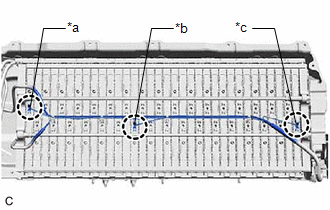
| (a) Engage the 3 claws of the hybrid battery thermistor (sensor portions) to install the hybrid battery thermistor to the HV battery. HINT: Install each hybrid battery thermistor (sensor portion) to the appropriate location shown in the illustration. |
|
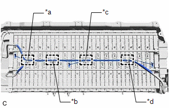
| (b) Engage the 4 clamps in the locations shown in the illustration. |
|
(c) Connect the battery voltage sensor connector.
(d) Engage the clamp.
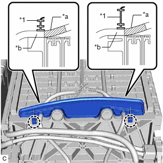
| (e) Engage the 2 claws to install the No. 1 hybrid battery packing to the HV battery. NOTICE: Align each piece of tape on the wire harness of the hybrid battery thermistor with the edge of the No. 1 hybrid battery packing as shown in the illustration and then engage the 2 claws to install the No. 1 hybrid battery packing to the HV battery. |
|
(f) Engage the clamp.
2. INSTALL NO. 1 HV BATTERY INTAKE DUCT LH
CAUTION:
Be sure to wear insulated gloves and protective goggles.
(a) Install the No. 1 HV battery intake duct LH to the HV battery with the clip.
(b) Engage the claw of hybrid battery thermistor (sensor portion) to connect the hybrid battery thermistor to the No. 1 HV battery intake duct LH.
3. INSTALL NO. 2 HYBRID BATTERY SHIELD SUB-ASSEMBLY
CAUTION:
Be sure to wear insulated gloves and protective goggles.
(a) Pull back the rear No. 1 HV battery shield and install the No. 2 hybrid battery shield sub-assembly to the HV battery.
HINT:
Pull back the rear No. 1 HV battery shield until there is sufficient clearance for the stud bolt of the No. 2 hybrid battery shield sub-assembly.
(b) Install the 5 nuts.
Torque:
7.5 N·m {76 kgf·cm, 66 in·lbf}
4. INSTALL HV BATTERY JUNCTION BLOCK ASSEMBLY
Click here .gif)
5. INSTALL UPPER HV BATTERY COVER SUB-ASSEMBLY
Click here
6. INSTALL HV BATTERY
Click here
READ NEXT:
 Components
COMPONENTS ILLUSTRATION *1 BATTERY SERVICE HOLE COVER *2 SERVICE PLUG GRIP ILLUSTRATION *1 CONNECTOR COVER ASSEMBLY *2 ENGINE ROOM MAIN WIRE Tightening torque for "Major
Removal
REMOVAL CAUTION / NOTICE / HINT The necessary procedures (adjustment, calibration, initialization or registration) that must be performed after parts are removed and installed, or replaced during HV b
SEE MORE:
Removal
REMOVAL CAUTION / NOTICE / HINT The necessary procedures (adjustment, calibration, initialization, or registration) that must be performed after parts are removed and installed, or replaced during mass air flow meter sub-assembly removal/installation are shown below. Necessary Procedures After Parts
System Voltage (BATT) Circuit Short to Ground or Open (P056014)
DESCRIPTION Auxiliary battery power is supplied to the BATT terminal of the hybrid vehicle control ECU in order to store DTCs and freeze frame data. Even if the power switch is turned off, back-up power is supplied. DTC No. Detection Item DTC Detection Condition Trouble Area MIL Warning
