Lexus ES: Removal
REMOVAL
CAUTION / NOTICE / HINT
The necessary procedures (adjustment, calibration, initialization or registration) that must be performed after parts are removed and installed, or replaced during HV battery junction block assembly removal/installation are shown below.
Necessary Procedures After Parts Removed/Installed/Replaced| Replaced Part or Performed Procedure | Necessary Procedure | Effect/Inoperative Function when Necessary Procedure not Performed | Link |
|---|---|---|---|
|
*: When performing learning using the Techstream.
Click here | |||
| Auxiliary battery terminal is disconnected/reconnected | Perform steering sensor zero point calibration | Lane Control System | |
| Pre-collision System | |||
| Parking Support Brake System* | |||
| Lighting System | |||
| Memorize steering angle neutral point | Parking assist monitor system | | |
| Panoramic view monitor system | | ||
| Initialize power trunk lid system | Power Trunk Lid System | | |
CAUTION:
-
Orange wire harnesses and connectors indicate high-voltage circuits. To prevent electric shock, always follow the procedure described in the repair manual.
.png)
Click here
.gif)
-
To prevent electric shock, wear insulated gloves when working on wire harnesses and components of the high voltage system.
.png)
NOTICE:
- After the power switch is turned off, the radio receiver assembly records various types of memory and settings. As a result, after turning the power switch off, make sure to wait at least 85 seconds before disconnecting the cable from the negative (-) auxiliary battery terminal. (for Audio and Visual System)
- After the power switch is turned off, the radio receiver assembly records various types of memory and settings. As a result, after turning the power switch off, make sure to wait at least 85 seconds before disconnecting the cable from the negative (-) auxiliary battery terminal. (for Navigation System)
PROCEDURE
1. REMOVE SERVICE PLUG GRIP
Click here
2. DISCONNECT ENGINE ROOM MAIN WIRE
Click here
3. REMOVE CONNECTOR COVER ASSEMBLY
Click here
4. CHECK TERMINAL VOLTAGE
Click here
5. INSTALL CONNECTOR COVER ASSEMBLY
Click here
6. CONNECT ENGINE ROOM MAIN WIRE
Click here
7. REMOVE NO. 2 INDOOR ELECTRICAL KEY ANTENNA ASSEMBLY
Click here
8. REMOVE REAR DOOR SCUFF PLATE LH
Click here
9. REMOVE REAR UNDER SIDE COVER LH
Click here
10. REMOVE REAR DOOR SCUFF PLATE RH
HINT:
Use the same procedure as for the LH side.
11. REMOVE REAR UNDER SIDE COVER RH
Click here
12. REMOVE REAR UNDER COVER
Click here
13. REMOVE REAR SEAT CUSHION LEG SUB-ASSEMBLY
Click here
14. REMOVE NO. 1 HV BATTERY COVER PANEL RH
Click here
15. DISCONNECT HV FLOOR UNDER WIRE
Click here
16. DISCONNECT FLOOR WIRE
CAUTION:
Be sure to wear insulated gloves.
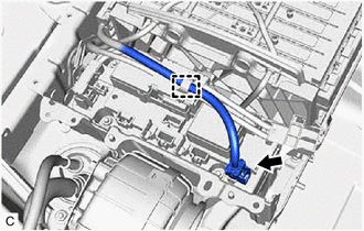
| (a) Disengage the clamp. |
|
.png)
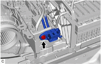
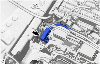
(b) Disconnect the electric vehicle battery plug assembly connector.
(c) Disconnect the HV battery junction block assembly connector.
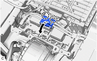
| (d) Disengage the 2 clamps to disconnect the floor wire. |
|
.png)
17. REMOVE NO. 1 HYBRID BATTERY EXHAUST DUCT
Click here
18. REMOVE UPPER HV BATTERY COVER SUB-ASSEMBLY
Click here
19. REMOVE HV BATTERY JUNCTION BLOCK ASSEMBLY
CAUTION:
Be sure to wear insulated gloves and protective goggles.
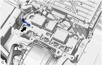
| (a) Remove the bolt and disconnect the electric vehicle battery plug assembly. |
|
| (b) Disconnect the HV battery junction block assembly connector. NOTICE: Insulate the disconnected connectors with insulating tape. |
|
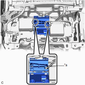
(c) Disengage the clamp.
| (d) Disengage the 2 claws and open the wiring harness protector. |
|
| (e) Disconnect the HV battery junction block assembly connector. NOTICE: Insulate the disconnected connectors with insulating tape. |
|
| (f) Using a screwdriver with its tip wrapped with protective tape, disengage the 2 claws and remove the wiring harness protector. |
|
| (g) Disconnect the HV battery junction block assembly connector. |
|
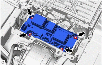
| (h) Remove the 4 nuts and HV battery junction block assembly from the HV battery. NOTICE: If the HV battery junction block assembly has been struck or dropped, replace it with a new one. |
|
READ NEXT:
 Inspection
INSPECTION PROCEDURE 1. INSPECT HV BATTERY JUNCTION BLOCK ASSEMBLY (a) Inspect SMRB: (1) Measure the resistance according to the value(s) in the table below. *a Component without harness connect
Installation
INSTALLATION PROCEDURE 1. INSTALL HV BATTERY JUNCTION BLOCK ASSEMBLY CAUTION: Be sure to wear insulated gloves and protective goggles. (a) Install the HV battery junction block assembly to the HV batt
SEE MORE:
Image from Camera for Parking Assist Monitor is Abnormal
DESCRIPTION The video signal from the rear television camera assembly is transmitted to the multi-display assembly. WIRING DIAGRAM CAUTION / NOTICE / HINT NOTICE:
If the cable was disconnected from and reconnected to the negative (-) battery terminal, the estimated course lines may not be displa
Removal
REMOVAL CAUTION / NOTICE / HINT The necessary procedures (adjustment, calibration, initialization or registration) that must be performed after parts are removed and installed, or replaced during engine water pump assembly removal/installation are shown below. Necessary Procedure After Parts Removed
