Lexus ES: Parts Location
PARTS LOCATION
ILLUSTRATION
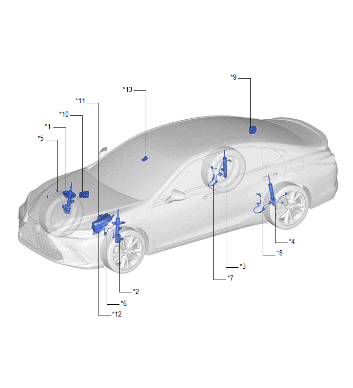
| *1 | FRONT ABSORBER CONTROL ACTUATOR RH (FRONT SHOCK ABSORBER ASSEMBLY RH) | *2 | FRONT ABSORBER CONTROL ACTUATOR LH (FRONT SHOCK ABSORBER ASSEMBLY LH) |
| *3 | REAR ABSORBER CONTROL ACTUATOR RH (REAR SHOCK ABSORBER ASSEMBLY RH) | *4 | REAR ABSORBER CONTROL ACTUATOR LH (REAR SHOCK ABSORBER ASSEMBLY LH) |
| *5 | SKID CONTROL SENSOR WIRE WITH SUSPENSION CONTROL RH | *6 | SKID CONTROL SENSOR WIRE WITH SUSPENSION CONTROL LH |
| *7 | SKID CONTROL SENSOR WIRE RH (NO. 1 PARKING BRAKE WIRE ASSEMBLY) | *8 | SKID CONTROL SENSOR WIRE LH (NO. 2 PARKING BRAKE WIRE ASSEMBLY) |
| *9 | ABSORBER CONTROL ECU | *10 | SKID CONTROL ECU (BRAKE ACTUATOR ASSEMBLY) |
| *11 | ECM | *12 | NO. 1 ENGINE ROOM RELAY BLOCK AND NO. 1 JUNCTION BLOCK ASSEMBLY - AVS RELAY - AVS FUSE |
| *13 | FORWARD RECOGNITION CAMERA | - | - |
ILLUSTRATION
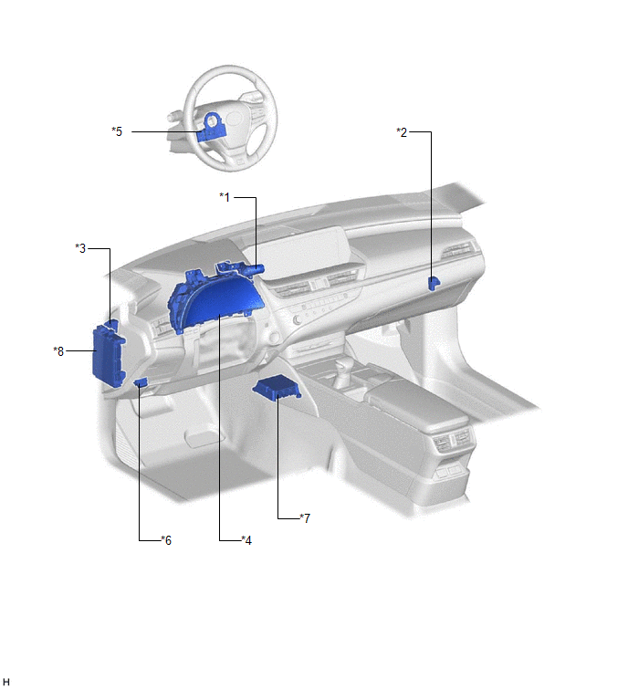
| *1 | DRIVE MODE SELECT SWITCH (COMBINATION SWITCH ASSEMBLY) | *2 | ACCELERATION SENSOR ASSEMBLY RH |
| *3 | ACCELERATION SENSOR ASSEMBLY LH | *4 | COMBINATION METER ASSEMBLY |
| *5 | STEERING SENSOR | *6 | DLC3 |
| *7 | AIRBAG ECU ASSEMBLY | *8 | INSTRUMENT PANEL JUNCTION BLOCK ASSEMBLY - ECU-IG1 NO. 3 FUSE |
| *9 | ENGINE STOP AND START ECU | - | - |
READ NEXT:
 System Diagram
SYSTEM DIAGRAM
System Description
SYSTEM DESCRIPTION ADAPTIVE VARIABLE SUSPENSION SYSTEM DESCRIPTION (a) The ECM judges the mode based on the input from the drive mode select switch (combination switch assembly). The absorber control
How To Proceed With Troubleshooting
CAUTION / NOTICE / HINT HINT:
Use the following procedure to troubleshoot the adaptive variable suspension system.
*: Use the Techstream.
PROCEDURE 1. VEHICLE BROUGHT TO WORKSHOP
SEE MORE:
Problem Symptoms Table
PROBLEM SYMPTOMS TABLE NOTICE: Before replacing the main body ECU (multiplex network body ECU), refer to Registration. for Gasoline Model: Click here for HV Model: Click here HINT: Use the table below to help determine the cause of problem symptoms. If multiple suspected areas are listed, the
Adjustment
ADJUSTMENT CAUTION / NOTICE / HINT NOTICE: Before adjusting the park/neutral position switch assembly, check that the shift lever is in N. PROCEDURE 1. SECURE VEHICLE (a) Fully apply the parking brake and chock a wheel. CAUTION:
Make sure to apply the parking brake and chock a wheel before perfor
