Lexus ES: Components
COMPONENTS
ILLUSTRATION
.png)
| *1 | BATTERY SERVICE HOLE COVER | *2 | SERVICE PLUG GRIP |
ILLUSTRATION
.png)
| *1 | CONNECTOR COVER ASSEMBLY | *2 | ENGINE ROOM MAIN WIRE |
.png) | Tightening torque for "Major areas involving basic vehicle performance such as moving/turning/stopping": N*m (kgf*cm, ft.*lbf) | .png) | N*m (kgf*cm, ft.*lbf): Specified torque |
ILLUSTRATION
.png)
| *1 | REAR UNDER COVER | *2 | REAR UNDER SIDE COVER LH |
| *3 | REAR UNDER SIDE COVER RH | *4 | REAR SEAT CUSHION LEG SUB-ASSEMBLY |
| *5 | REAR DOOR SCUFF PLATE RH | *6 | REAR DOOR SCUFF PLATE LH |
| | Tightening torque for "Major areas involving basic vehicle performance such as moving/turning/stopping": N*m (kgf*cm, ft.*lbf) | - | - |
ILLUSTRATION
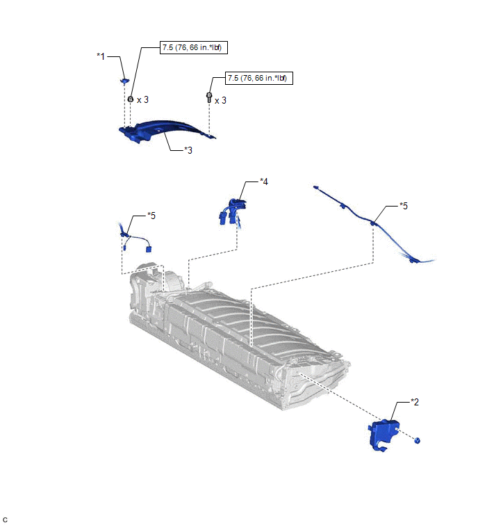
| *1 | BATTERY COVER LOCK STRIKER | *2 | NO. 1 HYBRID BATTERY EXHAUST DUCT |
| *3 | NO. 1 HV BATTERY COVER PANEL RH | *4 | HV FLOOR UNDER WIRE |
| *5 | FLOOR WIRE | - | - |
| | N*m (kgf*cm, ft.*lbf): Specified torque | - | - |
ILLUSTRATION
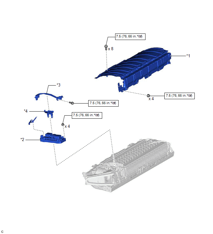
| *1 | UPPER HV BATTERY COVER SUB-ASSEMBLY | *2 | HV BATTERY JUNCTION BLOCK ASSEMBLY |
| *3 | ELECTRIC VEHICLE BATTERY PLUG ASSEMBLY | *4 | WIRING HARNESS PROTECTOR |
| | N*m (kgf*cm, ft.*lbf): Specified torque | - | - |
READ NEXT:
 Removal
REMOVAL CAUTION / NOTICE / HINT The necessary procedures (adjustment, calibration, initialization or registration) that must be performed after parts are removed and installed, or replaced during HV b
Inspection
INSPECTION PROCEDURE 1. INSPECT HV BATTERY JUNCTION BLOCK ASSEMBLY (a) Inspect SMRB: (1) Measure the resistance according to the value(s) in the table below. *a Component without harness connect
Installation
INSTALLATION PROCEDURE 1. INSTALL HV BATTERY JUNCTION BLOCK ASSEMBLY CAUTION: Be sure to wear insulated gloves and protective goggles. (a) Install the HV battery junction block assembly to the HV batt
SEE MORE:
Hybrid/EV Battery Current Sensor "A" Circuit Range/Performance (P0ABF00)
DESCRIPTION A battery current sensor is installed to the positive (+) terminal side of the HV battery and detects current flowing from the HV battery. The battery current sensor outputs voltage, which changes between 0 and 5 V according to the detected amperage, to the IB terminal of the battery vol
Precaution
PRECAUTION PRECAUTION FOR DISCONNECTING CABLE FROM NEGATIVE AUXILIARY BATTERY TERMINAL NOTICE: When disconnecting the cable from the negative (-) auxiliary battery terminal, initialize the following systems after the cable is reconnected. System Name See Procedure Lane Control System (for H
