Lexus ES: Discharging
DISCHARGING
PROCEDURE
1. DISCHARGING (WHEN USING THE LI-ION BATTERY DISCHARGER)
CAUTION:
Be sure to wear insulated gloves and protective goggles.
NOTICE:
Make sure to observe the following points when using the Li-ion battery discharger.- Set it in a secure, flat place.
- Set it in a dry place protected from dust and water.
- Set it in a position where illumination of the LED indicators can be observed.
- Do not block the ventilation holes or cooling fans.
(a) Select Li-ion battery connection cables
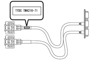
| (1) Confirm the type of the Li-ion battery connection cable as indicated by the tag shown in the illustration. (Type: TM4216-71) |
|
(b) Install Li-ion battery connection cable
| (1) Set the Li-ion battery discharger as shown in the illustration. |
|
.png)
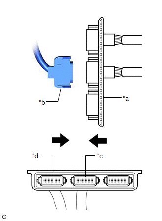
| (2) Connect the Li-ion battery connection cable connector (A) to the Li-ion battery discharger connector (A). NOTICE: Make sure that the connector is connected securely. |
|
.png)
| (3) Connect the Li-ion battery connection cable connector (B) to the Li-ion battery discharger connector (B). NOTICE: Make sure that the connector is connected securely. |
|
.png)
| (4) Set the Li-ion battery discharger as shown in the illustration. HINT: The Li-ion battery discharger is set on its side so that the ventilation holes will not be blocked. |
|
.png)
(c) Connect Li-ion battery connection cable
| (1) Connect the connector (orange) of the HV supply stack sub-assembly to be discharged to the Li-ion battery connection cable (orange). |
|
| (2) Confirm that all of the LED indicators are illuminated as shown in the following table. CAUTION: If all of the LED indicators of the Li-ion battery discharger listed in the following table are not illuminated, the HV supply stack sub-assembly cannot be discharged using the Li-ion battery discharger. Make sure to soak the HV supply stack sub-assembly in a salt water solution to complete discharging. LED Indicator Illumination Status (When discharge has started normally)
|
|
.png)
(3) Confirm that the cooling fans operate.
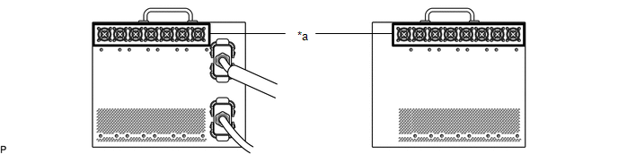
| *a | Cooling Fans | - | - |
HINT:
- To discharge the HV supply stack sub-assembly completely, continue discharging for at least 1 hour after the LED indicators have turned off.
- Discharge of a fully charged HV supply stack sub-assembly will complete within 5 hours (including 1 hour waiting time after the LED indicators have turned off).
(d) Confirm discharge completion
(1) Confirm that all of the LED indicators of the Li-ion battery discharger have turned off.
(2) Continue to discharge the HV battery for 1 hour after all of the LED indicators of the Li-ion battery discharger have turned off.
(e) Disconnect Li-ion battery connection cable
| (1) Disconnect the connector (orange) of the HV supply stack sub-assembly from the Li-ion battery connection cable (orange). |
|
(f) Remove Li-ion battery connection cable
| (1) Set the Li-ion battery discharger as shown in the illustration. |
|
.png)
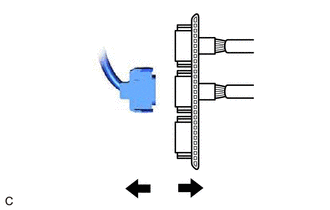
| (2) Disconnect the Li-ion battery connection cable connector (B) from the Li-ion battery discharger connector (B). |
|
.png)
| (3) Disconnect the Li-ion battery connection cable connector (A) from the Li-ion battery discharger connector (A). |
|
.png)
2. DISCHARGING (WHEN USING THE SALT WATER SOLUTION)
CAUTION:
Be sure to wear insulated gloves and protective goggles.
NOTICE:
- When discharging using salt water solution, first add a measured amount of water to the container, and then add the concentrated salt water solution.
- Calculate the salt water concentration based on the measured volume of water in the container so that a 1% salt water solution will be made after adding the concentrated salt water solution to the water in the container where the HV supply stack sub-assembly is set.
(a) Prepare HV supply stack sub-assembly
| (1) Set the HV supply stack sub-assembly in the container (A). |
|
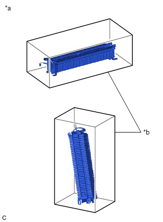
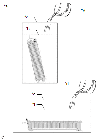
(b) Prepare to discharge (Add water to container)
| (1) Measure the water capacity of the container (B). HINT: Water capacity of the container (B) is assumed as X (liter). |
|
.png)
| (2) Using the container (B), add water to the container (A) until the HV supply stack sub-assembly is completely submerged. NOTICE: Make sure to record the times the container (B) was filled with water to add water to the container (A). |
|
(3) Using the following formula, calculate the amount of water added to the container (A).
Amount of water added to the container (A):
Y (liter) = Water capacity of the container (B) x Number of times the container (B) was filled with water to submerge the HV supply stack sub-assembly
HINT:
Amount of water added to the container (A) is assumed as Y (liter).
(c) Prepare salt water solution
| (1) While measuring the amount of water, fill about half of the container (B) with water. HINT: Amount of water added to the container (B) is assumed as Z (liter). |
|
.png)
(2) Calculate the amount of salt to be added to the container (A) so that a 1% salt water solution will be made.
Amount of Salt:
Amount of salt (kg) = (Y (liter) + Z (liter)) x 0.01
| (3) Add the calculated amount of salt to the container (B) and stir it thoroughly. |
|
.png)
(d) Add salt water solution
| (1) Add the concentrated salt water solution to the container (A). |
|
.png)
(e) Discharge
(1) Leave the HV supply stack sub-assembly as is for 24 hours or more until discharge is complete.
CAUTION:
- Do not place a lid on the container.
- Make sure to leave the HV supply stack sub-assembly and container as is for 24 hours or more.
- Display a warning sign to inform others that discharge is being performed.
(f) Confirm discharge completion
(1) Check that bubbles are not forming in the container.
NOTICE:
If bubbles are forming, discharge may not be completed yet. Do not place a lid on the container.
(g) Display a warning sign such as "DO NOT TOUCH! (DISCHARGE BEING PERFORMED) to inform others. Make a copy of the warning sign and place it near the HV supply stack sub-assembly being discharged.
.png)
READ NEXT:
 Components
COMPONENTS ILLUSTRATION *1 UPPER HV BATTERY COVER SUB-ASSEMBLY *2 HV BATTERY JUNCTION BLOCK ASSEMBLY *3 ELECTRIC VEHICLE BATTERY PLUG ASSEMBLY *4 WIRING HARNESS PROTECTOR N*
Removal
REMOVAL CAUTION / NOTICE / HINT The necessary procedures (adjustment, calibration, initialization or registration) that must be performed after parts are removed and installed, or replaced during hybr
SEE MORE:
Installation
INSTALLATION PROCEDURE 1. INSTALL NO. 2 RADIO BRACKET HINT: Perform this procedure only when replacement of the No. 2 radio bracket is necessary. (a) Install the No. 2 radio bracket with the 3 screws. 2. INSTALL NO. 1 RADIO BRACKET HINT: Perform this procedure only when replacement of the No. 1 radi
Lost Communication with Cruise Control Front Distance Range Sensor Signal Sensor or Center Missing Message (U023587)
DESCRIPTION The forward recognition camera and millimeter wave radar sensor assembly communicate via CAN communication. If there is an error in the communication with the millimeter wave radar sensor assembly, the forward recognition camera stores DTC U023587. DTC No. Detection Item DTC Detec
