Lexus ES: Pattern Select Switch Sport Mode Circuit
DESCRIPTION
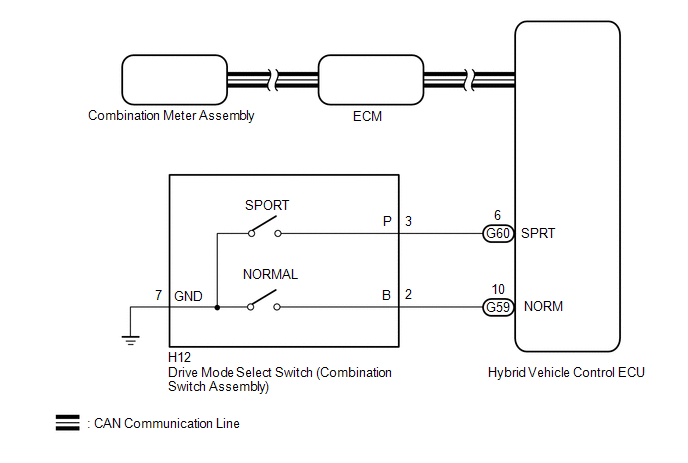
When selecting sport mode, the switch operation signal is sent to the hybrid vehicle control ECU. Following this, the system enters sport mode and the vehicle will be driven using sport mode. This signal is then transmitted from the hybrid vehicle control ECU via CAN to the combination meter assembly to illuminate the "Sport" indicator.
WIRING DIAGRAM
PROCEDURE
| 1. | READ VALUE USING TECHSTREAM (CAN BUS CHECK) |
Click here .gif)
| Result | Proceed to |
|---|---|
| All of the ECUs and sensors that are currently connected to the CAN communication system are displayed | A |
| None of the ECUs and sensors that are currently connected to the CAN communication system are displayed, or some of them are not displayed | B |
| B | .gif) | GO TO CAN COMMUNICATION SYSTEM |
|
.gif)
| 2. | CHECK DTC OUTPUT (HEALTH CHECK) |
Click here
| Result | Proceed to |
|---|---|
| No DTCs are output | A |
| DTCs are output | B |
| B | | GO TO DTC CHART |
|
| 3. | READ VALUE USING TECHSTREAM (SPORT MODE SWITCH, NORMAL MODE SWITCH) |
(a) Connect the Techstream to the DLC3.
(b) Turn the power switch on (IG).
(c) Enter the following menus: Powertrain / Hybrid Control / Data List / Sport Mode Switch, Normal Mode Switch.
Powertrain > Hybrid Control > Data List| Tester Display |
|---|
| Sport Mode Switch |
| Normal Mode Switch |
(d) Read the value displayed on the Techstream.
| Result | Proceed to |
|---|---|
| The Techstream display changes according to the drive mode select switch (combination switch assembly) operation | A |
| The Techstream display does not change according to the drive mode select switch (combination switch assembly) operation | B |
(e) Turn the power switch off.
| A | | GO TO PROBLEM SYMPTOMS TABLES |
|
| 4. | INSPECT DRIVE MODE SELECT SWITCH (COMBINATION SWITCH ASSEMBLY) (SPORT MODE, NORMAL MODE) |
Click here
| NG | | REPLACE DRIVE MODE SELECT SWITCH (COMBINATION SWITCH ASSEMBLY) |
|
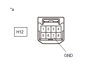
| 5. | CHECK HARNESS AND CONNECTOR (DRIVE MODE SELECT SWITCH (COMBINATION SWITCH ASSEMBLY) - BODY GROUND) |
(a) Disconnect the H12 drive mode select switch (combination switch assembly) connector.
| (b) Measure the resistance according to the value(s) in the table below. Standard Resistance:
|
|
(c) Reconnect the H12 drive mode select switch (combination switch assembly) connector.
| NG | | REPAIR OR REPLACE HARNESS OR CONNECTOR |
|
| 6. | CHECK HARNESS AND CONNECTOR (HYBRID VEHICLE CONTROL ECU - DRIVE MODE SELECT SWITCH (COMBINATION SWITCH ASSEMBLY)) |
(a) Disconnect the G59 and G60 hybrid vehicle control ECU connectors.
(b) Disconnect the H12 drive mode select switch (combination switch assembly) connector.
(c) Measure the resistance according to the value(s) in the table below.
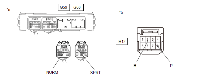
| *a | Rear view of wire harness connector (to Hybrid Vehicle Control ECU) | *b | Front view of wire harness connector (to Drive Mode Select Switch (Combination Switch Assembly)) |
Standard Resistance:
| Tester Connection | Condition | Specified Condition |
|---|---|---|
| G60-6 (SPRT) - H12-3 (P) | Always | Below 1 Ω |
| G60-6 (SPRT) or H12-3 (P) - Body ground | Always | 10 kΩ or higher |
| G59-10 (NORM) - H12-2 (B) | Always | Below 1 Ω |
| G59-10 (NORM) or H12-2 (B) - Body ground | Always | 10 kΩ or higher |
(d) Reconnect the H12 drive mode select switch (combination switch assembly) connector.
(e) Reconnect the G59 and G60 hybrid vehicle control ECU connectors.
| OK | | REPLACE HYBRID VEHICLE CONTROL ECU |
| NG | | REPAIR OR REPLACE HARNESS OR CONNECTOR |
READ NEXT:
 Pattern Select Switch Eco Mode Circuit
DESCRIPTION When selecting Eco drive mode, the drive mode select switch (combination switch assembly) (Eco drive mode) operation signal is sent to the air conditioning amplifier assembly. Following th
Indicator Circuit
DESCRIPTION In accordance with the shift lever position, each shift position indicator light will turn on. WIRING DIAGRAM PROCEDURE 1. CHECK SHIFT POSITION INDICATOR (a) Turn the power switc
Drive Start Control
DESCRIPTION The drive start control is controlled by the hybrid vehicle control ECU. If the hybrid vehicle control ECU determines that the shift lever and accelerator pedal are operated abnormally, hy
SEE MORE:
Initialization
INITIALIZATION INITIALIZE PARKING ASSIST MONITOR SYSTEM (a) When "!" mark is displayed on the image of the area behind the vehicle, perform the following procedure to correct the steering angle neutral point. (1) Fully turn the steering wheel to the right and left on flat ground. NOTICE: Memorizing
Camshaft Position Sensor "A" Bank 1 or Single Sensor Circuit Short to Ground (P034011,P034015)
DESCRIPTION The camshaft position sensor (for intake camshaft) (VV1 signal) consists of a magnet and MRE (Magneto Resistance Element). The intake camshaft has a timing rotor for the camshaft position sensor. When the intake camshaft rotates, changes occur in the air gaps between the timing rotor and
