Lexus ES: Removal
REMOVAL
CAUTION / NOTICE / HINT
The necessary procedures (adjustment, calibration, initialization or registration) that must be performed after parts are removed and installed, or replaced during hybrid battery thermistor removal/installation are shown below.
Necessary Procedures After Parts Removed/Installed/Replaced| Replaced Part or Performed Procedure | Necessary Procedure | Effect/Inoperative Function when Necessary Procedure not Performed | Link |
|---|---|---|---|
|
*: When performing learning using the Techstream.
Click here | |||
| Auxiliary battery terminal is disconnected/reconnected | Perform steering sensor zero point calibration | Lane Control System | |
| Pre-collision System | |||
| Parking Support Brake System* | |||
| Lighting System | |||
| Memorize steering angle neutral point | Parking assist monitor system | | |
| Panoramic view monitor system | | ||
| Initialize power trunk lid system | Power Trunk Lid System | | |
| Replacement of HV battery | Battery status info update | HV battery status information cannot be updated | |
CAUTION:
-
Orange wire harnesses and connectors indicate high-voltage circuits. To prevent electric shock, always follow the procedure described in the repair manual.
.png)
Click here
.gif)
-
To prevent electric shock, wear insulated gloves when working on wire harnesses and components of the high voltage system.
.png)
NOTICE:
- After the power switch is turned off, the radio receiver assembly records various types of memory and settings. As a result, after turning the power switch off, make sure to wait at least 85 seconds before disconnecting the cable from the negative (-) auxiliary battery terminal. (for Audio and Visual System)
- After the power switch is turned off, the radio receiver assembly records various types of memory and settings. As a result, after turning the power switch off, make sure to wait at least 85 seconds before disconnecting the cable from the negative (-) auxiliary battery terminal. (for Navigation System)
PROCEDURE
1. REMOVE HV BATTERY
Click here
2. REMOVE UPPER HV BATTERY COVER SUB-ASSEMBLY
Click here
3. REMOVE HV BATTERY JUNCTION BLOCK ASSEMBLY
Click here
4. REMOVE NO. 2 HYBRID BATTERY SHIELD SUB-ASSEMBLY
CAUTION:
Be sure to wear insulated gloves and protective goggles.
| (a) Remove the 5 nuts. |
|
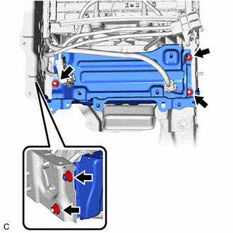
(b) Pull back the rear No. 1 HV battery shield and remove the No. 2 hybrid battery shield sub-assembly from the HV battery.
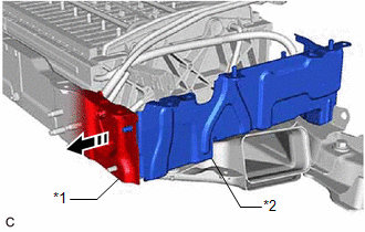
| *1 | Rear No. 1 HV Battery Shield |
| *2 | No. 2 Hybrid Battery Shield Sub-assembly |
.png) | Pull Back |
HINT:
Pull back the rear No. 1 HV battery shield until it is separated from the stud bolt of the No. 2 hybrid battery shield sub-assembly.
5. REMOVE NO. 1 HV BATTERY INTAKE DUCT LH
CAUTION:
Be sure to wear insulated gloves and protective goggles.
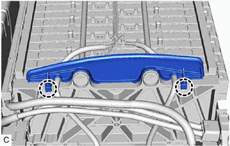
| (a) Remove the clip to disconnect the No. 1 HV battery intake duct LH from the HV battery. |
|
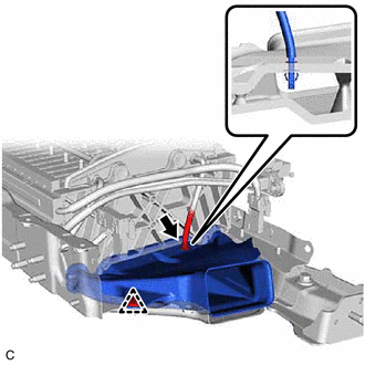
(b) Disengage the claw of hybrid battery thermistor (sensor portion) and remove the No. 1 HV battery intake duct LH.
6. REMOVE HYBRID BATTERY THERMISTOR
CAUTION:
Be sure to wear insulated gloves and protective goggles.
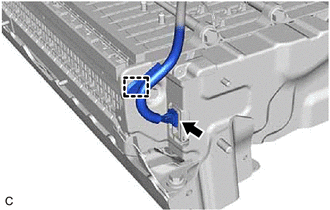
| (a) Disengage the clamp. |
|
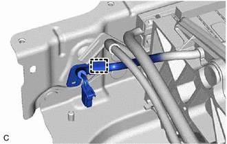
| (b) Disengage the 2 claws and remove the No. 1 hybrid battery packing from the HV battery. |
|
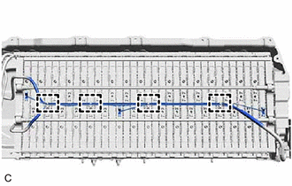
| (c) Disengage the clamp. |
|
(d) Disconnect the battery voltage sensor connector.
| (e) Disengage the 4 clamps. |
|
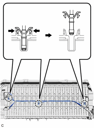
| (f) Disengage the 3 claws of the hybrid battery thermistor (sensor portions) and remove the hybrid battery thermistor from the HV battery. |
|
READ NEXT:
 Installation
INSTALLATION PROCEDURE 1. INSTALL HYBRID BATTERY THERMISTOR CAUTION: Be sure to wear insulated gloves and protective goggles. (a) Engage the 3 claws of the hybrid battery thermistor (sensor portion
Components
COMPONENTS ILLUSTRATION *1 BATTERY SERVICE HOLE COVER *2 SERVICE PLUG GRIP ILLUSTRATION *1 CONNECTOR COVER ASSEMBLY *2 ENGINE ROOM MAIN WIRE Tightening torque for "Major
SEE MORE:
Removal
REMOVAL CAUTION / NOTICE / HINT The necessary procedures (adjustment, calibration, initialization, or registration) that must be performed after parts are removed and installed, or replaced during side television camera assembly removal/installation are shown below. Necessary Procedure After Parts R
Components
COMPONENTS ILLUSTRATION *1 BLIND SPOT MONITOR COVER LH *2 BLIND SPOT MONITOR COVER RH *3 BLIND SPOT MONITOR SENSOR LH *4 BLIND SPOT MONITOR SENSOR RH N*m (kgf*cm, ft.*lbf) : Specified torque - -
