Lexus ES: Installation
INSTALLATION
PROCEDURE
1. INSTALL STUD BOLT
HINT:
If a stud bolt is deformed or its threads are damaged, replace it.
| (a) Using an E8 "TORX" socket wrench, install the 2 stud bolts to the exhaust manifold assembly LH (TWC: Front Catalyst). Torque: 19.5 N·m {199 kgf·cm, 14 ft·lbf} |
|
.png)
2. INSTALL EXHAUST MANIFOLD TO HEAD GASKET (for Bank 2)
(a) Install a new exhaust manifold to head gasket (for Bank 2) to the cylinder head sub-assembly.
3. INSTALL EXHAUST MANIFOLD ASSEMBLY LH (TWC: Front Catalyst)
(a) Temporarily install the exhaust manifold assembly LH (TWC: Front Catalyst) with the 4 nuts.
(b) Temporarily install the No. 2 manifold stay to the exhaust manifold assembly LH (TWC: Front Catalyst) and cylinder block sub-assembly with the bolt and nut.
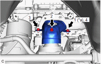
| (c) Using a 12 mm deep socket wrench, tighten the 4 nuts in the order shown in the illustration. Torque: 21 N·m {214 kgf·cm, 15 ft·lbf} |
|
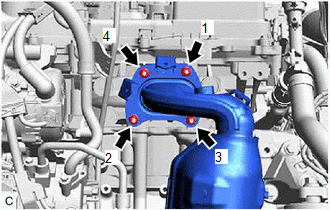
(d) Tighten the bolt and nut in the order shown in the illustration.
.png) | Bolt |
.png) | Nut |
Torque:
Nut :
35 N·m {357 kgf·cm, 26 ft·lbf}
Bolt :
34 N·m {347 kgf·cm, 25 ft·lbf}
4. CONNECT NO. 5 WATER BY-PASS HOSE
(a) Engage the 2 clamps to connect the No. 5 water by-pass hose and No. 6 water by-pass hose to the hose clamp.
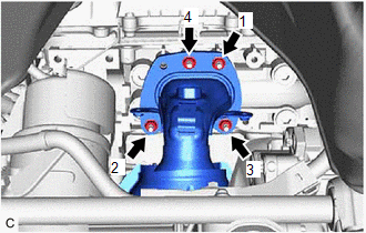
5. INSTALL NO. 2 EXHAUST MANIFOLD HEAT INSULATOR
| (a) Install the No. 2 exhaust manifold heat insulator to the exhaust manifold assembly LH (TWC: Front Catalyst) with the 3 bolts in the order shown in the illustration. Torque: 8.5 N·m {87 kgf·cm, 75 in·lbf} |
|
6. INSTALL ENGINE OIL LEVEL DIPSTICK GUIDE
Click here .gif)
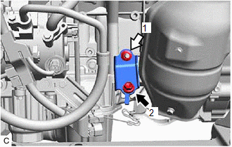
7. INSTALL AIR FUEL RATIO SENSOR (for Bank 2)
Click here
8. INSTALL COOL AIR INTAKE DUCT SEAL
Click here
9. INSTALL V-BANK COVER SUB-ASSEMBLY
Click here
10. INSTALL EXHAUST MANIFOLD TO HEAD GASKET (for Bank 1)
(a) Install a new exhaust manifold to head gasket (for Bank 1) to the cylinder head sub-assembly RH.
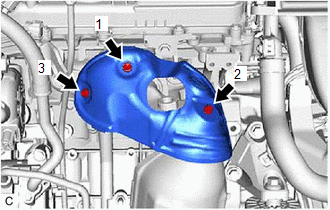
11. INSTALL EXHAUST MANIFOLD ASSEMBLY RH (TWC: Front Catalyst)
(a) Temporarily install the exhaust manifold assembly RH (TWC: Front Catalyst) with the 4 nuts.
| (b) Using a 12 mm deep socket wrench, tighten the 4 nuts in the order shown in the illustration. Torque: 21 N·m {214 kgf·cm, 15 ft·lbf} |
|
12. INSTALL NO. 1 EXHAUST MANIFOLD HEAT INSULATOR
| (a) Install the No. 1 exhaust manifold heat insulator to the exhaust manifold assembly RH (TWC: Front Catalyst) with the 3 bolts in the order shown in the illustration. Torque: 8.5 N·m {87 kgf·cm, 75 in·lbf} |
|
13. INSTALL AIR FUEL RATIO SENSOR (for Bank 1)
Click here
14. INSTALL FRONT EXHAUST PIPE ASSEMBLY (TWC: Rear Catalyst)
(a) Install 3 new gaskets to the front exhaust pipe assembly (TWC: Rear Catalyst).
(b) Connect the front exhaust pipe assembly (TWC: Rear Catalyst) to the exhaust pipe support.
(c) Install the front exhaust pipe assembly (TWC: Rear Catalyst) with 4 new bolts and 4 new nuts.
Torque:
43 N·m {438 kgf·cm, 32 ft·lbf}
(d) Engage the 2 wire harness clamps.
(e) Connect the 2 heated oxygen sensor connectors.
15. INSTALL NO. 1 EXHAUST PIPE SUPPORT BRACKET (for Lower Side)
Click here
16. INSTALL BODY MOUNTING PLATE
Click here
17. INSTALL FRONT FLOOR COVER LH
Click here
18. INSTALL FRONT FLOOR COVER RH
Click here
19. INSPECT FOR EXHAUST GAS LEAK
Click here
20. INSTALL NO. 2 ENGINE UNDER COVER
Click here
21. INSTALL NO. 1 ENGINE UNDER COVER
Click here
22. INSTALL FRONT WHEEL OPENING EXTENSION PAD LH
Click here
23. INSTALL FRONT WHEEL OPENING EXTENSION PAD RH
Click here
READ NEXT:
 Components
COMPONENTS ILLUSTRATION *A Type A *B Type B *1 FRONT FLOOR COVER RH - - N*m (kgf*cm, ft.*lbf): Specified torque - - ILLUSTRATION *A Type A *B Type B *1
Removal
REMOVAL CAUTION / NOTICE / HINT The necessary procedures (adjustment, calibration, initialization or registration) that must be performed after parts are removed and installed, or replaced during fron
SEE MORE:
Communication Error from ECM to VSC Invalid Serial Data Received (P163181)
DESCRIPTION The skid control ECU (brake actuator assembly) sends signals such as brake request signals to the ECM. When the ECM detects logic error signals sent from the skid control ECU (brake actuator assembly) for a certain period of time, DTC P163181 is stored. DTC No. Detection Item DTC
Data List / Active Test
DATA LIST / ACTIVE TEST DATA LIST NOTICE: In the table below, the values listed under "Normal Condition" are reference values. Do not depend solely on these reference values when deciding whether a part is faulty or not. HINT: Using the Techstream to read the Data List allows the values or states of
