Lexus ES: Components
COMPONENTS
ILLUSTRATION
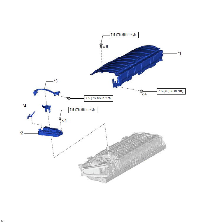
| *1 | UPPER HV BATTERY COVER SUB-ASSEMBLY | *2 | HV BATTERY JUNCTION BLOCK ASSEMBLY |
| *3 | ELECTRIC VEHICLE BATTERY PLUG ASSEMBLY | *4 | WIRING HARNESS PROTECTOR |
.png) | N*m (kgf*cm, ft.*lbf): Specified torque | - | - |
ILLUSTRATION
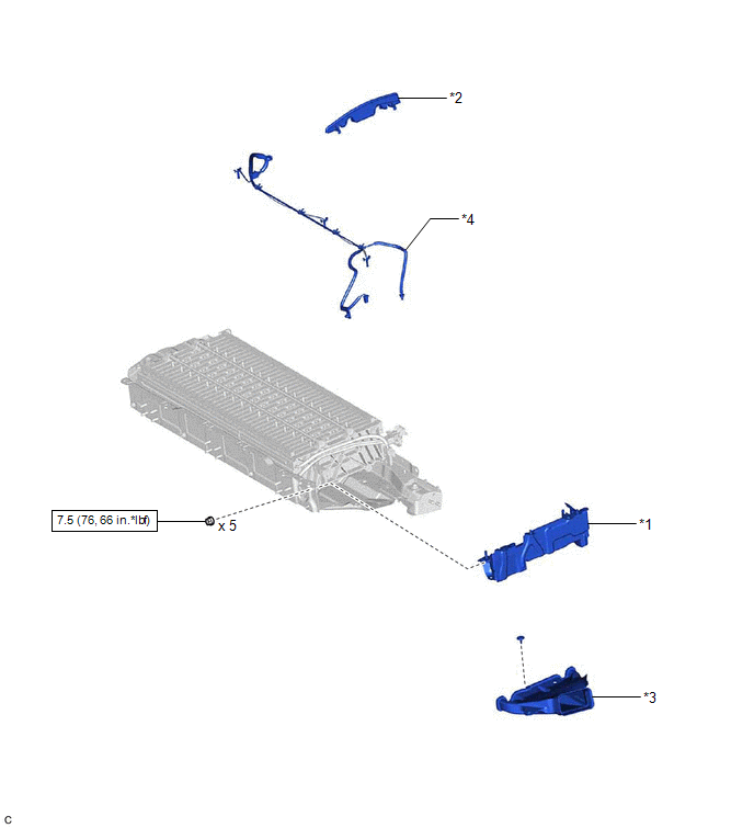
| *1 | NO. 2 HYBRID BATTERY SHIELD SUB-ASSEMBLY | *2 | NO. 1 HYBRID BATTERY PACKING |
| *3 | NO. 1 HV BATTERY INTAKE DUCT LH | *4 | HYBRID BATTERY THERMISTOR |
| | N*m (kgf*cm, ft.*lbf): Specified torque | - | - |
READ NEXT:
 Removal
REMOVAL CAUTION / NOTICE / HINT The necessary procedures (adjustment, calibration, initialization or registration) that must be performed after parts are removed and installed, or replaced during hybr
Installation
INSTALLATION PROCEDURE 1. INSTALL HYBRID BATTERY THERMISTOR CAUTION: Be sure to wear insulated gloves and protective goggles. (a) Engage the 3 claws of the hybrid battery thermistor (sensor portion
SEE MORE:
Parts Location
PARTS LOCATION ILLUSTRATION *1 CANISTER (CHARCOAL CANISTER ASSEMBLY) *2 FUEL TANK CAP ASSEMBLY *3 PCV VALVE (VENTILATION VALVE SUB-ASSEMBLY) *4 PURGE VALVE (PURGE VSV) *5 ECM *6 ENGINE ROOM RELAY BLOCK AND JUNCTION BLOCK ASSEMBLY - EFI-MAIN NO. 1 RELAY - EFI-MAIN NO. 1
Front Crankshaft Oil Seal
ComponentsCOMPONENTS ILLUSTRATION *1 CRANKSHAFT PULLEY ASSEMBLY *2 TIMING CHAIN COVER OIL SEAL *3 CRANKSHAFT PULLEY BOLT *4 V-RIBBED BELT N*m (kgf*cm, ft.*lbf): Specified torque ● Non-reusable part MP grease - - InstallationINSTALLATION CAUTION / NOTI
© 2016-2026 Copyright www.lexguide.net
