Lexus ES: Components
COMPONENTS
ILLUSTRATION
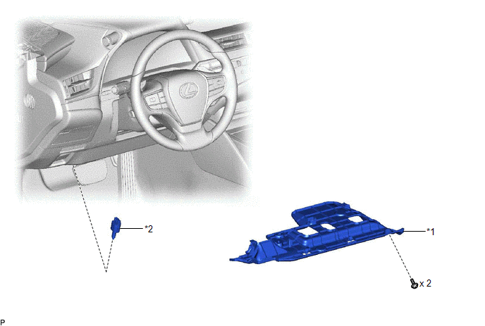
| *1 | NO. 1 INSTRUMENT PANEL UNDER COVER SUB-ASSEMBLY | *2 | STOP LIGHT SWITCH ASSEMBLY |
READ NEXT:
 On-vehicle Inspection
ON-VEHICLE INSPECTION PROCEDURE 1. INSPECT STOP LIGHT SWITCH ASSEMBLY (a) Disconnect the A80 stop light switch assembly connector. *a Front view of wire harness connector (to Stop Li
Removal
REMOVAL PROCEDURE 1. REMOVE NO. 1 INSTRUMENT PANEL UNDER COVER SUB-ASSEMBLY Click here 2. REMOVE STOP LIGHT SWITCH ASSEMBLY (a) Disconnect the connector. (b) Turn the stop light swit
Installation
INSTALLATION PROCEDURE 1. INSTALL STOP LIGHT SWITCH ASSEMBLY (a) Insert the stop light switch assembly until the threaded sleeve hits the pedal as shown in the illustration. *1 Stop Light Switch
SEE MORE:
Stereo Component Amplifier Disconnected (B15D3)
DESCRIPTION The radio receiver assembly and stereo component amplifier assembly are connected by AVC-LAN communication lines. This DTC is stored when an AVC-LAN communication error occurs between the radio receiver assembly and stereo component amplifier assembly. DTC No. Detection Item DTC D
Steering Angle Sensor Failure (C1626)
DESCRIPTION This DTC is stored if the rear television camera assembly receives a signal via CAN communication from the steering sensor that indicates an internal malfunction. DTC No. Detection Item DTC Detection Condition Trouble Area C1626 Steering Angle Sensor Failure A fail flag
© 2016-2026 Copyright www.lexguide.net
