Lexus ES: On-vehicle Inspection
ON-VEHICLE INSPECTION
PROCEDURE
1. INSPECT STOP LIGHT SWITCH ASSEMBLY
| (a) Disconnect the A80 stop light switch assembly connector. |
|
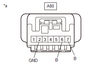
(b) Measure the voltage and resistance on the wire harness side connector according to the value(s) in the table below.
Standard Voltage:
| Tester Connection | Condition | Specified Condition |
|---|---|---|
|
*1: for HV Model
*2: for Gasoline Model | ||
| A80-7 (B) - A80-2 (GND) | Always | 11 to 14 V |
| A80-6 (B) - A80-2 (GND) | Power switch on (IG)*1 | 11 to 14 V |
| Engine switch on (IG)*2 | ||
Standard Resistance:
| Tester Connection | Condition | Specified Condition |
|---|---|---|
| A80-2 (GND) - Body ground | Always | Below 1 Ω |
If the result is not as specified, repair or replace the wire harness or connector.
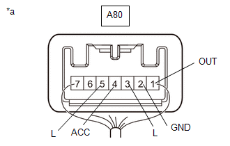
(c) Connect A80 the stop light switch assembly connector.
| (d) Measure the voltage according to the value(s) in the table below. Standard Voltage:
If the result is not as specified, replace the stop light switch assembly. |
| |||||||||||||||||||||||||||||||||||||
READ NEXT:
 Removal
REMOVAL PROCEDURE 1. REMOVE NO. 1 INSTRUMENT PANEL UNDER COVER SUB-ASSEMBLY Click here 2. REMOVE STOP LIGHT SWITCH ASSEMBLY (a) Disconnect the connector. (b) Turn the stop light swit
Installation
INSTALLATION PROCEDURE 1. INSTALL STOP LIGHT SWITCH ASSEMBLY (a) Insert the stop light switch assembly until the threaded sleeve hits the pedal as shown in the illustration. *1 Stop Light Switch
SEE MORE:
Data List / Active Test
DATA LIST / ACTIVE TEST DATA LIST NOTICE:
Some Data List values may vary significantly if there are slight differences in the environment in which the vehicle is operating when measurements are obtained. Variations may also occur due to aging of the vehicle. Due to these considerations, it is not
DC/DC Converter Enable Component Internal Failure (P1CCC96)
DESCRIPTION The DC/DC converter converts the DC 244.8 V of the HV battery into DC 12 V in order to supply power to areas such as the vehicle lighting system, audio system and various ECUs. Additionally, it charges the auxiliary battery. A transistor bridge circuit initially converts DC 244.8 V into
