Lexus ES: Stereo Component Amplifier Disconnected (B15D3)
DESCRIPTION
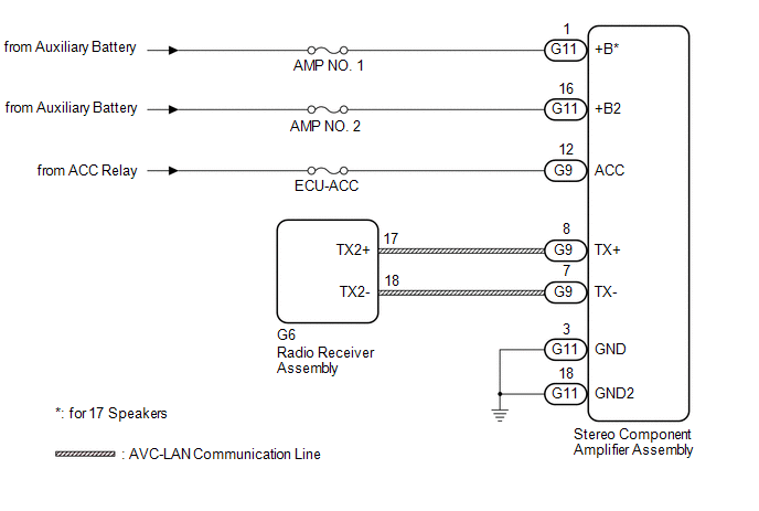
The radio receiver assembly and stereo component amplifier assembly are connected by AVC-LAN communication lines.
This DTC is stored when an AVC-LAN communication error occurs between the radio receiver assembly and stereo component amplifier assembly.
| DTC No. | Detection Item | DTC Detection Condition | Trouble Area |
|---|---|---|---|
| B15D3 | Stereo Component Amplifier Disconnected | A device that is listed in the AVC-LAN connected device record of the master unit is missing |
|
HINT:
The radio receiver assembly is the master unit.
WIRING DIAGRAM
CAUTION / NOTICE / HINT
NOTICE:
-
Depending on the parts that are replaced during vehicle inspection or maintenance, performing initialization, registration or calibration may be needed. Refer to Precaution for Audio and Visual System.
Click here
.gif)
-
When replacing the radio receiver assembly, always replace it with a new one. If a radio receiver assembly which was installed to another vehicle is used, the following may occur:
- A communication malfunction DTC may be stored.
- The radio receiver assembly may not operate normally.
- Inspect the fuses for circuits related to this system before performing the following procedure.
PROCEDURE
| 1. | CHECK DTC |
(a) If DTC B15C3 is output, perform troubleshooting for DTC B15C3 first.
| Result | Proceed to |
|---|---|
| DTC B15C3 is not output. | A |
| DTC B15C3 is output. | B |
| B | .gif) | GO TO DTC B15C3 |
|
.gif)
| 2. | CHECK OPTIONAL COMPONENTS (INCLUDING ASSOCIATED WIRING) |
(a) Check that optional components (including associated wiring) which generate radio waves are not installed.
| Result | Proceed to |
|---|---|
| Optional components (including associated wiring) are installed. | A |
| Optional components (including associated wiring) are not installed. | B |
HINT:
- Electrical noise from radio waves generated by optional components or the wiring for those components may affect AVC-LAN communication.
- This DTC may be stored when an AVC-LAN communication error occurs due to electrical noise.
| B | | GO TO STEP 4 |
|
| 3. | REMOVE OPTIONAL COMPONENTS (INCLUDING ASSOCIATED WIRING) |
(a) Remove optional components (including associated wiring).
NOTICE:
Do not remove optional components or associated wiring without the permission of the customer.
|
| 4. | CHECK DTC |
(a) Clear the DTCs.
Body Electrical > Navigation System > Clear DTCs(b) Recheck for DTCs and check that no DTCs are output.
Body Electrical > Navigation System > Trouble CodesOK:
No DTCs are output.
| OK | | END |
|
| 5. | CHECK HARNESS AND CONNECTOR (STEREO COMPONENT AMPLIFIER ASSEMBLY POWER SOURCE) |
(a) Disconnect the G11 and G9 stereo component amplifier assembly connectors.
(b) Measure the resistance according to the value(s) in the table below.
Standard Resistance:
| Tester Connection | Condition | Specified Condition |
|---|---|---|
| G11-3 (GND) - Body ground | Always | Below 1 Ω |
| G11-18 (GND2) - Body ground | Always | Below 1 Ω |
(c) Measure the voltage according to the value(s) in the table below.
Standard Voltage:
| Tester Connection | Condition | Specified Condition |
|---|---|---|
| G11-1 (+B) - G11-3 (GND)* | Power switch off | 11 to 14 V |
| G11-16 (+B2) - G11-3 (GND) | Power switch off | 11 to 14 V |
| G9-12 (ACC) - G11-3 (GND) | Power switch on (ACC) | 11 to 14 V |
- *: for 17 Speakers
| NG | | REPAIR OR REPLACE HARNESS OR CONNECTOR |
|
| 6. | CHECK HARNESS AND CONNECTOR (RADIO RECEIVER ASSEMBLY - STEREO COMPONENT AMPLIFIER ASSEMBLY) |
(a) Disconnect the G6 radio receiver assembly connector.
(b) Disconnect the G9 stereo component amplifier assembly connector.
(c) Measure the resistance according to the value(s) in the table below.
Standard Resistance:
| Tester Connection | Condition | Specified Condition |
|---|---|---|
| G6-17 (TX2+) - G9-8 (TX+) | Always | Below 1 Ω |
| G6-18 (TX2-) - G9-7 (TX-) | Always | Below 1 Ω |
| G6-17 (TX2+) or G9-8 (TX+) - Body ground | Always | 10 kΩ or higher |
| G6-18 (TX2-) or G9-7 (TX-) - Body ground | Always | 10 kΩ or higher |
| NG | | REPAIR OR REPLACE HARNESS OR CONNECTOR |
|
| 7. | REPLACE STEREO COMPONENT AMPLIFIER ASSEMBLY |
(a) Replace the stereo component amplifier assembly with a new or known good one.
Click here
(b) Clear the DTCs.
Body Electrical > Navigation System > Clear DTCs(c) Recheck for DTCs and check that no DTCs are output.
Body Electrical > Navigation System > Trouble CodesOK:
No DTCs are output.
| OK | | END |
| NG | | REPLACE RADIO RECEIVER ASSEMBLY |
READ NEXT:
 Display Disconnected (B15D6)
DESCRIPTION The multi-display assembly and radio receiver assembly are connected by AVC-LAN communication lines. This DTC is stored when an AVC-LAN communication error occurs between the multi-display
Operation Panel Disconnected (B15D9)
DESCRIPTION The air conditioning control assembly and multi-display assembly are connected by an AVC-LAN communication line. When an AVC-LAN communication error occurs between the multi-display assemb
Telematics Transceiver Disconnected (B15DB)
DESCRIPTION If the radio receiver assembly cannot detect the DCM (telematics transceiver) for a certain period of time (90 seconds) after the power switch is turned on (ACC) and the radio receiver ass
SEE MORE:
Registration
REGISTRATION CAUTION / NOTICE / HINT NOTICE:
When the automatic transaxle assembly is replaced, the transaxle compensation code must be registered to the ECM (proceed to Procedure 1).
After the automatic transaxle assembly is installed, the Quick Response (QR) code label will be positioned where
Inspection
INSPECTION PROCEDURE 1. INSPECT LUGGAGE DOOR OPENING CANCEL SWITCH ASSEMBLY (a) Check the resistance. (1) Measure the resistance according to the value(s) in the table below. Standard Resistance: Tester Connection Switch Condition Specified Condition 2 (B) - 1 (L) Switch on Below
