
Lexus ES: Components
COMPONENTS
ILLUSTRATION
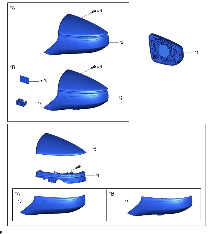
| *A | w/o Panoramic View Monitor System | *B | w/ Panoramic View Monitor System |
| *1 | OUTER MIRROR | *2 | OUTER MIRROR COVER ASSEMBLY |
| *3 | OUTER MIRROR LOWER COVER | *4 | SIDE TURN SIGNAL LIGHT ASSEMBLY |
| *5 | OUTER MIRROR UPPER COVER | *6 | OUTER MIRROR TAPE |
| *7 | CAMERA CONNECTOR CLAMP | - | - |
| ● | Non-reusable part | - | - |
READ NEXT:
 Removal
REMOVAL CAUTION / NOTICE / HINT The necessary procedures (adjustment, calibration, initialization, or registration) that must be performed after parts are removed and installed, or replaced during sid
Inspection
INSPECTION PROCEDURE 1. INSPECT SIDE TURN SIGNAL LIGHT ASSEMBLY LH *a Component without harness connected (Side Turn Signal Light Assembly LH) (a) Apply auxiliary battery voltage to the side
Installation
INSTALLATION CAUTION / NOTICE / HINT HINT:
Use the same procedure for the RH side and LH side.
The following procedure is for the LH side.
PROCEDURE 1. INSTALL SIDE TURN SIGNAL LIGHT ASSEMBLY
SEE MORE:
Automatic High Beam Camera (B124C)
DESCRIPTION The main body ECU (multiplex network body ECU) detects a high beam headlight illumination request signal of the automatic high beam system from the forward recognition camera. DTC No. Detection Item DTC Detection Condition Trouble Area DTC Output from B124C Automatic Hig
Removal
REMOVAL CAUTION / NOTICE / HINT NOTICE: This procedure includes the removal of small-head bolts. Refer to Small-Head Bolts of Basic Repair Hint to identify the small-head bolts. Click here PROCEDURE 1. DRAIN ENGINE COOLANT (for Engine) Click here 2. DISCONNECT NO. 2 RADIATOR HOSE Click here 3
© 2016-2026 Copyright www.lexguide.net
