Lexus ES: Removal
REMOVAL
CAUTION / NOTICE / HINT
The necessary procedures (adjustment, calibration, initialization, or registration) that must be performed after parts are removed and installed, or replaced during side turn signal light assembly removal/installation are shown below.
Necessary Procedure After Parts Removed/Installed/Replaced (for HV Model)| Replaced Part or Performed Procedure | Necessary Procedure | Effect/Inoperative Function when Necessary Procedure not Performed | Link |
|---|---|---|---|
| Side television camera view adjustment | Panoramic View Monitor System (for HV Model) | for Initialization for Calibration |
| Replaced Part or Performed Procedure | Necessary Procedure | Effect/Inoperative Function when Necessary Procedure not Performed | Link |
|---|---|---|---|
| Side television camera view adjustment | Panoramic View Monitor System (for Gasoline Model) | for Initialization for Calibration |
HINT:
- Use the same procedure for the RH side and LH side.
- The following procedure is for the LH side.
PROCEDURE
1. REMOVE OUTER MIRROR
Click here .gif)
2. REMOVE OUTER MIRROR COVER ASSEMBLY
Click here
3. REMOVE OUTER MIRROR LOWER COVER
Click here
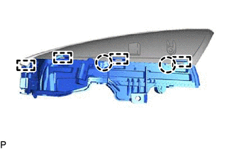
4. REMOVE SIDE TURN SIGNAL LIGHT ASSEMBLY
| (a) Disengage the 2 claws and 4 guides to remove the side turn signal light assembly. |
|
READ NEXT:
 Inspection
INSPECTION PROCEDURE 1. INSPECT SIDE TURN SIGNAL LIGHT ASSEMBLY LH *a Component without harness connected (Side Turn Signal Light Assembly LH) (a) Apply auxiliary battery voltage to the side
Installation
INSTALLATION CAUTION / NOTICE / HINT HINT:
Use the same procedure for the RH side and LH side.
The following procedure is for the LH side.
PROCEDURE 1. INSTALL SIDE TURN SIGNAL LIGHT ASSEMBLY
SEE MORE:
Drive Motor "A" Inverter Actuator Stuck Open (P0A7872)
DTC SUMMARY MALFUNCTION DESCRIPTION This DTC is stored when the motor generator control system is malfunctioning and current does not flow as commanded. The cause of this malfunction may be one of the following: Internal inverter malfunction
Inverter with converter assembly internal circuit malfu
Evaporative Emission System Incorrect Purge Flow Actuator Stuck On (P04417E,P04417F,P04419C)
DTC SUMMARY DTC No. Detection Item DTC Detection Condition Trouble Area MIL Memory Note P04417E Evaporative Emission System Incorrect Purge Flow Actuator Stuck On The stabilized EVAP system pressure is higher than [second reference pressure x 0.2] and the purge VSV is judged a
