Lexus ES: System Diagram
Lexus ES (XZ10) Service Manual / Engine & Hybrid System / 2gr-fks (engine Control) / Ignition System / System Diagram
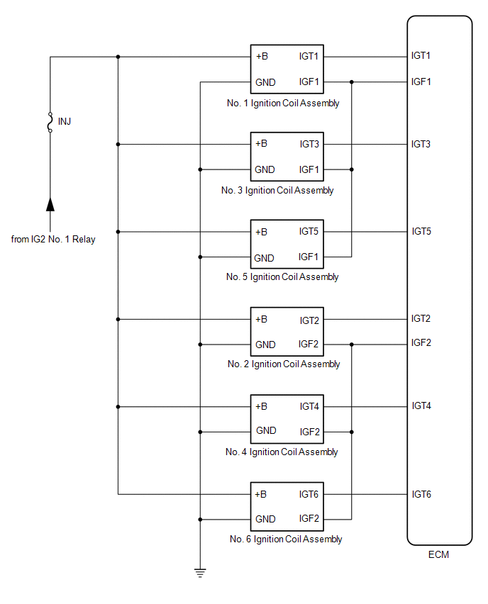
SYSTEM DIAGRAM
READ NEXT:
 On-vehicle Inspection
ON-VEHICLE INSPECTION CAUTION / NOTICE / HINT CAUTION: To prevent injury due to contact with an operating V-ribbed belt or cooling fan, keep your hands and clothing away from the V-ribbed belt and coo
Components
COMPONENTS ILLUSTRATION *1 KNOCK CONTROL SENSOR (for Bank 1) *2 KNOCK CONTROL SENSOR (for Bank 2) N*m (kgf*cm, ft.*lbf): Specified torque * For use with a union nut wrench
SEE MORE:
HD Radio Tuner Malfunction (B1551,B15A0,B15B3,B15B4,B15B7,B15BA,B15F9)
DESCRIPTION These DTCs are stored when a malfunction occurs in the radio receiver assembly. DTC No. Detection Item DTC Detection Condition Trouble Area B1551 HD Radio Tuner Malfunction When any of the following conditions is met:
"HD Radio" tuner decoder malfunction
"HD Radio"
Front Passenger Side Power Window Auto Up / Down Function does not Operate with Front Passenger Side Power Window Switch
DESCRIPTION If the manual up and down functions operate normally but the auto up and down functions do not, the power window control system may be in fail-safe mode. If power window initialization has not been performed, the auto up and down functions will not operate. Click here WIRING DIAGRAM C
© 2016-2026 Copyright www.lexguide.net
