Lexus ES: System Diagram
SYSTEM DIAGRAM
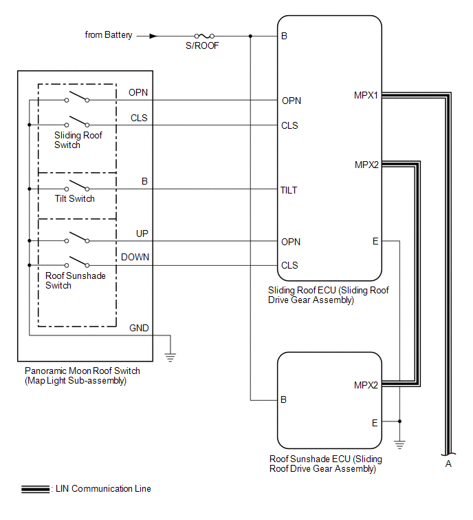
 Communication Table
 | Sender | Receiver | Signal | Line |
|---|---|---|---|
| Main Body ECU (Multiplex Network Body ECU) | Sliding Roof ECU (Sliding Roof Drive Gear Assembly) |
| LIN |
| Main Body ECU (Multiplex Network Body ECU) | Roof Sunshade ECU (Sliding Roof Drive Gear Assembly) |
| LIN |
| Sliding Roof ECU (Sliding Roof Drive Gear Assembly) | Main Body ECU (Multiplex Network Body ECU) | Sliding roof glass position signal | LIN |
| Sliding Roof ECU (Sliding Roof Drive Gear Assembly) | Roof Sunshade ECU (Sliding Roof Drive Gear Assembly) |
| LIN |
| Roof Sunshade ECU (Sliding Roof Drive Gear Assembly) | Sliding Roof ECU (Sliding Roof Drive Gear Assembly) |
| LIN |
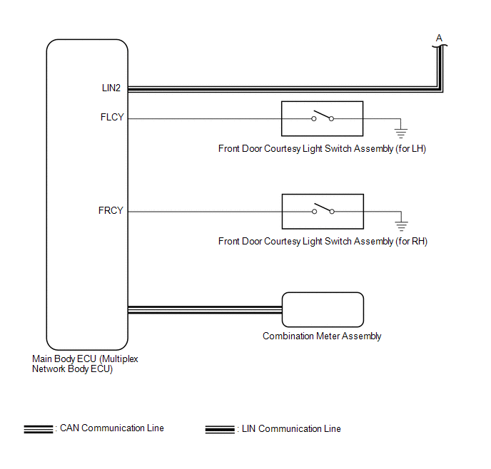
| Combination Meter Assembly | Main Body ECU (Multiplex Network Body ECU) | Vehicle speed signal | CAN |
| Main Body ECU (Multiplex Network Body ECU) | Combination Meter Assembly | Sliding roof open warning request signal | CAN |
READ NEXT:
 System Description
SYSTEM DESCRIPTION PANORAMIC MOON ROOF SYSTEM DESCRIPTION (a) The panoramic moon roof system controls the sliding roof operation using the sliding roof ECU (sliding roof drive gear assembly) and roof
How To Proceed With Troubleshooting
CAUTION / NOTICE / HINT HINT:
Use the following procedure to troubleshoot the panoramic moon roof system.
*: Use the Techstream.
PROCEDURE 1. VEHICLE BROUGHT TO WORKSHOP
NEXT
Operation Check
OPERATION CHECK CHECK AUTO OPERATION FUNCTION (FOR SLIDING ROOF) NOTICE:
Make sure that initialization has been completed before performing this inspection.
Click here
The sliding roof auto ope
SEE MORE:
Reassembly
REASSEMBLY CAUTION / NOTICE / HINT NOTICE: This procedure includes the installation of small-head bolts. Refer to Small-Head Bolts of Basic Repair Hint to identify the small-head bolts. Click here PROCEDURE 1. INSTALL STRAIGHT PIN NOTICE: It is not necessary to remove the straight pins unless they
Slip Indicator Light Remains ON
DESCRIPTION This procedure is for troubleshooting when the slip indicator light remains on but no DTCs are output. The skid control ECU (brake actuator assembly) controls the slip indicator light in the combination meter assembly via CAN communication. The slip indicator light blinks during VSC and/
