Lexus ES: Components
Lexus ES (XZ10) Service Manual / Engine & Hybrid System / 2gr-fks (engine Control) / Knock Sensor / Components
COMPONENTS
ILLUSTRATION
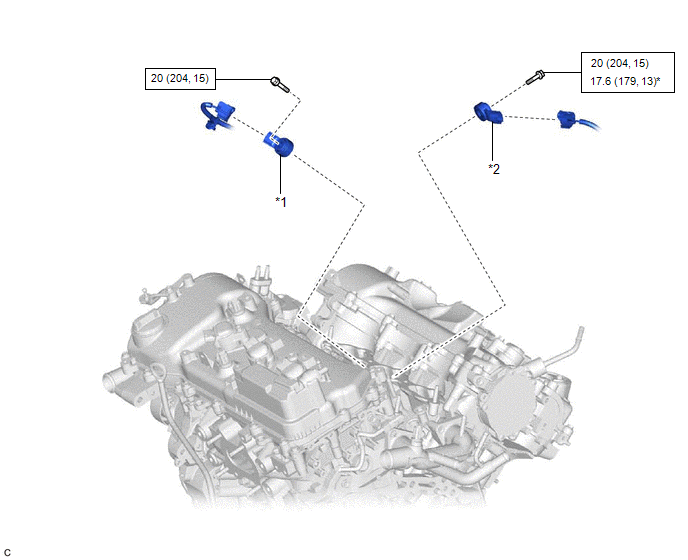
| *1 | KNOCK CONTROL SENSOR (for Bank 1) | *2 | KNOCK CONTROL SENSOR (for Bank 2) |
.png) | N*m (kgf*cm, ft.*lbf): Specified torque | * | For use with a union nut wrench |
READ NEXT:
 Removal
REMOVAL CAUTION / NOTICE / HINT The necessary procedures (adjustment, calibration, initialization or registration) that must be performed after parts are removed and installed, or replaced during knoc
Inspection
INSPECTION PROCEDURE 1. INSPECT KNOCK CONTROL SENSOR (a) Measure the resistance according to the value(s) in the table below. Standard Resistance: Tester Connection Condition Specified Cond
Installation
INSTALLATION PROCEDURE 1. INSTALL KNOCK CONTROL SENSOR HINT: Perform "Inspection After Repair" after replacing a knock control sensor. Click here (a) Temporarily install the 2 knock control sensors
SEE MORE:
Components
COMPONENTS ILLUSTRATION *1 CENTRAL GATEWAY ECU (NETWORK GATEWAY ECU) *2 ECU INTEGRATION BOX RH *3 GLOVE COMPARTMENT DOOR ASSEMBLY - -
Components
COMPONENTS ILLUSTRATION *1 FRONT DIFFERENTIAL CASE FRONT TAPERED ROLLER BEARING (INNER RACE) *2 FRONT DIFFERENTIAL CASE FRONT TAPERED ROLLER BEARING (OUTER RACE) *3 FRONT DIFFERENTIAL CASE REAR TAPERED ROLLER BEARING (INNER RACE) *4 FRONT DIFFERENTIAL CASE REAR TAPERED ROLLER BEA
© 2016-2026 Copyright www.lexguide.net
