Lexus ES: System Description
SYSTEM DESCRIPTION
BRIEF DESCRIPTION
(a) The Controller Area Network (CAN) is a serial data communication system for real time application. It is a vehicle multiplex communication system which has a high communication speed and the ability to detect malfunctions.
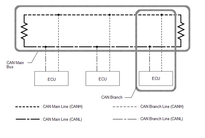
(b) Using the CANH and CANL bus lines as a pair, CAN communication is performed using a voltage differential. (A base voltage is applied to the pair of lines and a voltage differential is created when communicating.)
(c) Many ECUs or sensors installed to the vehicle operate by sharing information and communicating with each other.
(d) 2 resistors which are necessary for communication are used in a CAN bus main line.
DEFINITION OF TERMS
(a) Central bus
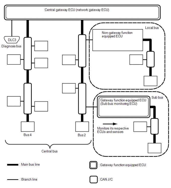
(1) The central bus is a term used to describe all buses directly connected to the central gateway ECU (network gateway ECU).
HINT:
A bus is displayed as Bus on the "Communication Bus Check" screen of the Techstream.
(b) Sub bus
(1) A sub bus is a bus that has a gateway function equipped ECU in order to communicate with the central bus and other sub buses.
HINT:
- A sub bus is displayed as Sub bus on the "Communication Bus Check" screen of the Techstream.
- When Sub bus is selected on the "Communication Bus Check" screen, ECUs and sensors connected to non-CAN networks such as LIN may also be displayed in addition to the ECUs and sensors connected to sub buses in the CAN network.
(c) Local bus
(1) A local bus is a bus that does not have the ability to communicate with other buses. ECUs and sensors on a local bus can only communicate with other ECUs and sensors on the same bus.
(d) CAN J/C
(1) A CAN junction connector is a connector that connects branch lines to a main bus.
(e) Main bus
(1) A main bus line is the wire harness that runs between the 2 terminating resistors of a bus.
(f) Branch
(1) A branch line is a wire harness that connects an ECU or sensor to a main bus line.
(g) Terminating resistors
(1) Terminating resistors which maintain a stable signal inside the CAN bus are installed. 2 resistors of 120 Ω each located at each end of the bus are necessary.
READ NEXT:
 System Diagram
SYSTEM DIAGRAM (a) The CAN communication system is composed of 5 buses. CAN Main Bus Line Terminating Resistor CAN Branch Line * Gateway Function Equipped ECU Bus Monitor
Parts Location
PARTS LOCATION ILLUSTRATION *1 SWING GRILLE ACTUATOR ASSEMBLY *2 MILLIMETER WAVE RADAR SENSOR ASSEMBLY *3 HEADLIGHT ECU SUB-ASSEMBLY RH *4 INVERTER WITH CONVERTER ASSEMBLY *5
Precaution
PRECAUTION NOTICE FOR INITIALIZATION NOTICE: When disconnecting the cable from the negative (-) auxiliary battery terminal, initialize the following systems after the cable is reconnected. System
SEE MORE:
Disassembly
DISASSEMBLY CAUTION / NOTICE / HINT HINT:
Use the same procedure for the RH side and LH side.
The following procedure is for the LH side.
PROCEDURE 1. REMOVE HEADLIGHT ECU SUB-ASSEMBLY Click here 2. REMOVE HEADLIGHT GASKET Click here 3. REMOVE HEADLIGHT RIM (for TMC Made) Click here 4.
System Description
SYSTEM DESCRIPTION FUNCTION OF COMPONENTS (a) The parking support brake system consists of the following components: Component Function Clearance Warning ECU Assembly
Sends the drive force request signals and control status signals to the hybrid vehicle control ECU and skid control ECU
