Lexus ES: System Diagram
SYSTEM DIAGRAM
(a) The CAN communication system is composed of 5 buses.
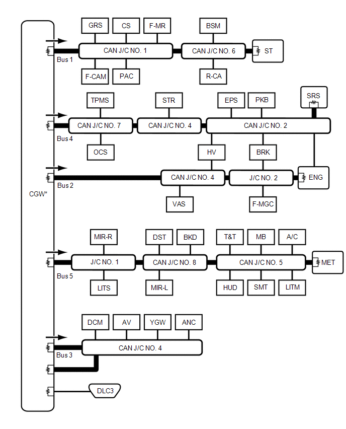
 | CAN Main Bus Line |  | Terminating Resistor |
 | CAN Branch Line | * | Gateway Function Equipped ECU |
.png) | Bus Monitoring Direction | - | - |
| Connected to | Code | ECU/Sensor Name | CAN DTC Storage | Note |
|---|---|---|---|---|
| - | CGW | Central Gateway ECU (Network Gateway ECU) | - | - |
| - | DLC3 | DLC3 | - | - |
| Bus 1 | GRS | Swing Grille Actuator Assembly | - | - |
| F-CAM | Forward Recognition Camera | Available | - | |
| CS | Clearance Warning ECU Assembly | Available | w/ Parking Support Alert System | |
| PAC | Parking Assist ECU | Available | w/ Panoramic View Monitor System | |
| F-MR | Millimeter Wave Radar Sensor Assembly | Available | - | |
| BSM | Blind Spot Monitor Sensor RH | Available | w/ Blind Spot Monitor System | |
| R-CA | Rear Television Camera Assembly | Available | - | |
| CAN J/C NO. 1 | No. 1 CAN Junction Connector | - | - | |
| CAN J/C NO. 6 | No. 6 CAN Junction Connector | - | - | |
| ST | No. 1 CAN Junction Terminal | - | - | |
| Bus 2 | HV | Hybrid Vehicle Control ECU | Available | - |
| VAS | Vehicle Approaching Speaker Controller | Available | - | |
| BRK | Brake Booster with Master Cylinder Assembly | Available | - | |
| F-MGC | Inverter with Converter Assembly | Available | - | |
| ENG | ECM | Available | - | |
| CAN J/C NO. 4 | No. 4 CAN Junction Connector | - | - | |
| J/C NO. 2 | No. 2 Junction Connector | - | - | |
| Bus 3 | DCM | DCM (Telematics Transceiver) | Available | w/ Telematics Transceiver |
| AV | Radio Receiver Assembly | Available | - | |
| YGW | Option Connector (Bus Buffer ECU) | - | w/ CAN Compatible Optional Devices | |
| ANC | Stereo Component Equalizer Assembly | Available | - | |
| CAN J/C NO. 4 | No. 4 CAN Junction Connector | - | - | |
| Bus 4 | TPMS | Tire Pressure Warning ECU and Receiver | Available | - |
| OCS | Occupant Detection ECU | Available | - | |
| STR | Steering Sensor | - | - | |
| EPS | Rack and Pinion Power Steering Gear Assembly | Available | - | |
| HV | Hybrid Vehicle Control ECU | Available | - | |
| PKB | Brake Actuator Assembly | Available | - | |
| BRK | Brake Booster with Master Cylinder Assembly | Available | - | |
| ENG | ECM | Available | - | |
| SRS | Airbag ECU Assembly | Available | - | |
| CAN J/C NO. 2 | No. 2 CAN Junction Connector | - | - | |
| CAN J/C NO. 4 | No. 4 CAN Junction Connector | - | - | |
| CAN J/C NO. 7 | No. 7 CAN Junction Connector | - | - | |
| Bus 5 | MIR-R | Outer Mirror Control ECU Assembly RH | Available | w/ Seat Position Memory System |
| LITS | Headlight ECU Sub-assembly RH | Available | - | |
| DST | Position Control ECU Assembly LH | - | w/ Seat Position Memory System | |
| MIR-L | Outer Mirror Control ECU Assembly LH | Available | w/ Seat Position Memory System | |
| BKD | Luggage Closer Motor Assembly | Available | w/ Power Trunk Lid System | |
| T&T | Multiplex Tilt and Telescopic ECU | Available | w/ Power Tilt and Power Telescopic System | |
| HUD | Meter Mirror Sub-assembly | Available | w/ Headup Display System | |
| MB | Main Body ECU (Multiplex Network Body ECU) | Available | Connected to LIN communication system | |
| SMT | Certification ECU (Smart Key ECU Assembly) | Available | - | |
| A/C | Air Conditioning Amplifier Assembly | Available | - | |
| LITM | Headlight ECU Sub-assembly LH | Available | - | |
| MET | Combination Meter Assembly | Available | - | |
| CAN J/C NO. 5 | No. 5 CAN Junction Connector | - | - | |
| CAN J/C NO. 8 | No. 8 CAN Junction Connector | - | - | |
| J/C NO. 1 | No. 1 Junction Connector | - | - |
READ NEXT:
 Parts Location
PARTS LOCATION ILLUSTRATION *1 SWING GRILLE ACTUATOR ASSEMBLY *2 MILLIMETER WAVE RADAR SENSOR ASSEMBLY *3 HEADLIGHT ECU SUB-ASSEMBLY RH *4 INVERTER WITH CONVERTER ASSEMBLY *5
Precaution
PRECAUTION NOTICE FOR INITIALIZATION NOTICE: When disconnecting the cable from the negative (-) auxiliary battery terminal, initialize the following systems after the cable is reconnected. System
SEE MORE:
Disassembly
DISASSEMBLY PROCEDURE 1. REMOVE KICK DOOR CONTROL SENSOR WITH BRACKET (w/ Hands Free Power Trunk Lid) Click here 2. REMOVE REAR CENTER ULTRASONIC SENSOR (w/ Parking Support Alert System) Click here HINT: Use the same procedure for the RH side and LH side. 3. REMOVE REAR CORNER ULTRASONIC SENSOR
Components
COMPONENTS ILLUSTRATION *1 BATTERY SERVICE HOLE COVER *2 SERVICE PLUG GRIP ILLUSTRATION *1 CONNECTOR COVER ASSEMBLY *2 ENGINE ROOM MAIN WIRE Tightening torque for "Major areas involving basic vehicle performance such as moving/turning/stopping": N*m (kgf*cm, ft.*lbf)
