Lexus ES: Precaution
PRECAUTION
NOTICE FOR INITIALIZATION
NOTICE:
When disconnecting the cable from the negative (-) auxiliary battery terminal, initialize the following systems after the cable is reconnected.
| System | See Procedure |
|---|---|
| Lane Control System | |
| Parking Support Brake System | |
| Parking Assist Monitor System | |
| Panoramic View Monitor System | |
| Pre-collision System | |
| Power Trunk Lid System | |
| Lighting System |
CAN COMMUNICATION SYSTEM TROUBLESHOOTING
(a) Because the order of diagnosis is important to allow correct diagnosis, make sure to begin troubleshooting using How to Proceed with Troubleshooting when CAN communication system related DTCs are output.
Click here .gif)
(b) Precaution for steering system handling
(1) Be careful when replacing parts. Incorrect replacement could affect the performance of the steering system and result in hazardous driving.
Click here
(c) Precaution for SRS airbag system handling
NOTICE:
This vehicle is equipped with a Supplemental Restraint System (SRS) which includes parts such as airbags for the driver and front passenger. Failure to carry out service operations in the correct sequence could cause unexpected SRS deployment during servicing and may cause a serious accident. Before servicing (including removal or installation of parts, inspection or replacement), be sure to read Precaution for SRS.
Click here
(d) Precaution for when disconnecting a wire harness from a CAN junction connector
(1) When disconnecting a wire harness from a CAN junction connector, use tape or tags to identify each connector and make sure to reconnect each connector to its original location on the CAN junction connector.
HINT:
- Reconnecting a connector to a location other than its original location on the CAN junction connector will not affect system performance. However, reconnecting connectors to their original locations makes future maintenance easier and avoids negative effects on wire harnesses, such as excessive tension.
-
For information on how to identify the ECUs or sensors connected to the CAN junction connector, refer to Terminals of ECU.
Click here
(e) Bus line repair
(1) After repairing a bus line with solder, wrap the repaired area with electrical tape.
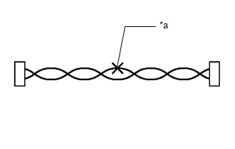
| *a | Soldered Area to Be Wrapped with Electrical Tape |
NOTICE:
- When installing, make sure that these lines are twisted, because CAN bus lines are likely to be influenced by electrical noise if the bus lines are not twisted.
- Ensure that there is no gap between the CANH wire and CANL wire.
- Make sure that the distance between the first twist of the wires and the connector is less than 80 mm (3.15 in).
- When repairing the CAN bus lines, do not change the length of the lines. (Make sure that the length of the CANH bus line and CANL bus line are the same.)
(2) Do not use bypass wiring between connectors.
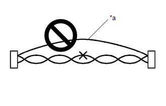
| *a | Bypass Wire |
NOTICE:
- The ability of the twisted bus lines to resist interference will be lost if bypass wiring is used.
- Do not use a twisted pair of wires for bypass wiring.
(f) Connector handling
(1) When checking resistance with a tester, insert the tester probes from the backside (harness side) of the connector.
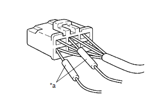
| *a | Tester Probe |
(2) When it is not possible to insert the tester from the backside of the connector, using service wires, measure from the front side of the connector.
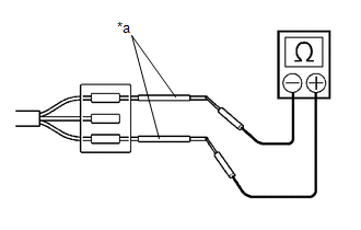
| *a | Service Wire |
(g) Precaution for when replacing a gateway function equipped ECU (sub bus monitoring ECU)
(1) When replacing a gateway equipped function ECU (sub bus monitoring ECU) with one which was installed to another vehicle, perform initialization of the sub bus monitoring ECU in order to clear stored bus information.
Click here
NOTICE:
If the stored bus information does not match the current sub bus configuration, DTCs may be stored and fail-safe functions may operate.
HINT:
It is not necessary to perform initialization of a gateway monitoring ECU (sub bus monitoring ECU) when using a sub bus monitoring ECU which was installed to another vehicle with the same sub bus configuration.
(h) Precautions for when a gateway function equipped ECU (sub bus monitor ECU) detects communication DTCs for ECUs not connected to the ECU
(1) Refer to precautions when replacing a gateway function equipped ECU (sub bus monitoring ECU) and initialize the connection information of the ECU.
(2) Clear the DTCs and check that no DTCs are output.
(i) Difference between genuine navigation receivers/radio and display receivers and optional navigation receivers/radio and display receivers
(1) Some optional navigation receivers/radio and display receivers are available as CAN compatible devices. Be aware that some optional navigation receivers/radio and display receivers do not have the same diagnostic features or characteristics of genuine navigation receivers/radio and display receivers.
NOTICE:
- Optional navigation receivers/radio and display receivers receive data from the CAN communication system. However, most optional navigation receivers/radio and display receivers do not send signals to the CAN bus main line.
- Most optional navigation receivers/radio and display receivers will not be displayed on the "CAN Bus Check" screen of the Techstream.
- When checking for DTCs using the Techstream, DTCs for optional navigation receivers/radio and display receivers will not be displayed on the Techstream.
SENSOR EXPRESSIONS
(a) The descriptions for the blind spot monitor sensors differ depending on the system. The expressions listed in the table below are used in this Repair Manual.
| Part Name | Actual Part Name |
|---|---|
| Blind spot monitor sensor LH (A) | Blind spot monitor sensor LH |
| Blind spot monitor sensor RH (B) | Blind spot monitor sensor RH |
READ NEXT:
 Tire Pressure Monitor ECU Communication Stop Mode
DESCRIPTION Detection Item Symptom Trouble Area Tire Pressure Monitor ECU Communication Stop Mode Any of the following conditions are met:
Communication stop for "Tire Pressure" is ind
Front Camera Module Communication Stop Mode
DESCRIPTION Detection Item Symptom Trouble Area Front Camera Module Communication Stop Mode Any of the following conditions are met:
Communication stop for "Front Camera Module" is ind
SEE MORE:
Monitor Drive Pattern
MONITOR DRIVE PATTERN MONITOR DRIVE PATTERN FOR ECT CAUTION: Perform the following procedure on a level surface while strictly observing all traffic laws and speed limits. HINT: Performing this drive pattern is one method to simulate ECM (ECT) malfunction detection conditions. Some DTCs may not be d
Installation
INSTALLATION PROCEDURE 1. INSTALL DCM (TELEMATICS TRANSCEIVER) 2. INSTALL NO. 1 TELEPHONE BRACKET (a) Install the No. 1 telephone bracket with the screw. 3. INSTALL TELEPHONE BRACKET (a) Install the telephone bracket with the screw. 4. INSTALL DCM (TELEMATICS TRANSCEIVER) WITH BRACKET (a) Connect ea
