
Lexus ES: Disassembly
DISASSEMBLY
CAUTION / NOTICE / HINT
HINT:
- Use the same procedure for the RH side and LH side.
- The following procedure is for the LH side.
PROCEDURE
1. REMOVE HEADLIGHT ECU SUB-ASSEMBLY
Click here .gif)
2. REMOVE HEADLIGHT GASKET
Click here
3. REMOVE HEADLIGHT RIM (for TMC Made)
Click here
4. REMOVE NO. 2 HEADLIGHT FITTING RIM (for TMC Made)
Click here
5. REMOVE FRONT TURN SIGNAL LIGHT BULB
(a) Turn the headlight cord with the front turn signal light bulb as shown in the illustration to disconnect them as a unit.
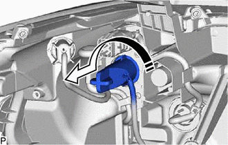
.png) | Disconnect in this Direction |
(b) Remove the front turn signal light bulb from the headlight cord.
6. REMOVE FRONT SIDE MARKER LIGHT BULB
(a) Turn the headlight cord with the front side marker light bulb as shown in the illustration to disconnect them as a unit.
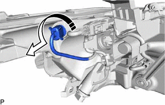
| | Disconnect in this Direction |
(b) Remove the front side marker light bulb from the headlight cord.
7. REMOVE HEADLIGHT CORD (for TMC Made)
| (a) Disconnect the connector. |
|
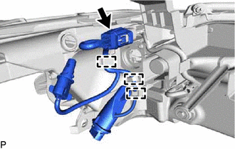
(b) Disengage the 3 clamps to remove the headlight cord.
8. REMOVE HEADLIGHT UNIT ASSEMBLY (for TMC Made)
9. REMOVE HEADLIGHT BRACKET (for TMC Made)
| (a) Disengage the claw to disconnect the No. 2 headlight cord. |
|
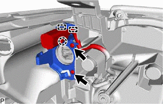
(b) Remove the 2 screws.
(c) Disengage the 2 guides to remove the headlight bracket.
10. REMOVE HEADLIGHT SEAL (for TMC Made)
Click here
READ NEXT:
 Adjustment
ADJUSTMENT CAUTION / NOTICE / HINT HINT:
Use the same procedure for the RH side and LH side.
The following procedure is for the LH side.
PROCEDURE 1. PREPARE VEHICLE FOR HEADLIGHT AIM ADJUSTME
Reassembly
REASSEMBLY CAUTION / NOTICE / HINT HINT:
Use the same procedure for the RH side and LH side.
The following procedure is for the LH side.
PROCEDURE 1. INSTALL HEADLIGHT SEAL (for TMC Made) Clic
Installation
INSTALLATION CAUTION / NOTICE / HINT HINT:
Use the same procedure for the RH side and LH side.
The following procedure is for the LH side.
PROCEDURE 1. INSTALL HEADLIGHT ASSEMBLY Click here
SEE MORE:
ANC ECU EEPROM Data Memory Failure (B1AA044)
DESCRIPTION This DTC is stored when a malfunction occurs in the stereo component equalizer assembly. DTC No. Detection Item DTC Detection Condition Trouble Area B1AA044 ANC ECU EEPROM Data Memory Failure Stereo component equalizer assembly malfunction Stereo component equalizer as
Rear Power Window RH Auto Up / Down Function does not Operate with Rear Power Window Switch RH
DESCRIPTION If the manual up and down functions operate normally but the auto up and down functions do not, the power window control system may be in fail-safe mode. If power window initialization has not been performed, the auto up and down functions will not operate. Click here WIRING DIAGRAM C
