Lexus ES: Parts Location
PARTS LOCATION
ILLUSTRATION
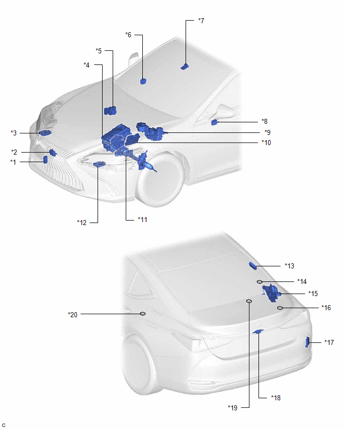
| *1 | SWING GRILLE ACTUATOR ASSEMBLY | *2 | MILLIMETER WAVE RADAR SENSOR ASSEMBLY |
| *3 | HEADLIGHT ECU SUB-ASSEMBLY RH | *4 | INVERTER WITH CONVERTER ASSEMBLY |
| *5 | BRAKE ACTUATOR ASSEMBLY | *6 | OUTER MIRROR CONTROL ECU ASSEMBLY RH (w/ Seat Position Memory System) |
| *7 | FORWARD RECOGNITION CAMERA | *8 | OUTER MIRROR CONTROL ECU ASSEMBLY LH (w/ Seat Position Memory System) |
| *9 | BRAKE BOOSTER WITH MASTER CYLINDER ASSEMBLY | *10 | ECM |
| *11 | RACK AND PINION POWER STEERING GEAR ASSEMBLY | *12 | HEADLIGHT ECU SUB-ASSEMBLY LH |
| *13 | TIRE PRESSURE WARNING ECU AND RECEIVER | *14 | NO. 7 CAN JUNCTION CONNECTOR |
| *15 | LUGGAGE CLOSER MOTOR ASSEMBLY (w/ Power Trunk Lid System) | *16 | NO. 6 CAN JUNCTION CONNECTOR |
| *17 | BLIND SPOT MONITOR SENSOR RH (w/ Blind Spot Monitor System) | *18 | REAR TELEVISION CAMERA ASSEMBLY |
| *19 | NO. 1 CAN JUNCTION TERMINAL | *20 | NO. 8 CAN JUNCTION CONNECTOR |
ILLUSTRATION
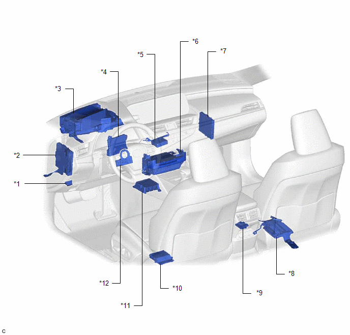
| *1 | DLC3 | *2 | HYBRID VEHICLE CONTROL ECU |
| *3 | METER MIRROR SUB-ASSEMBLY (w/ Headup Display System) | *4 | AIR CONDITIONING AMPLIFIER ASSEMBLY |
| *5 | VEHICLE APPROACHING SPEAKER CONTROLLER | *6 | RADIO RECEIVER ASSEMBLY |
| *7 | CERTIFICATION ECU (SMART KEY ECU ASSEMBLY) | *8 | PARKING ASSIST ECU (w/ Panoramic View Monitor System) |
| *9 | OCCUPANT DETECTION ECU | *10 | POSITION CONTROL ECU ASSEMBLY LH (w/ Seat Position Memory System) |
| *11 | AIRBAG ECU ASSEMBLY | *12 | STEERING SENSOR |
ILLUSTRATION
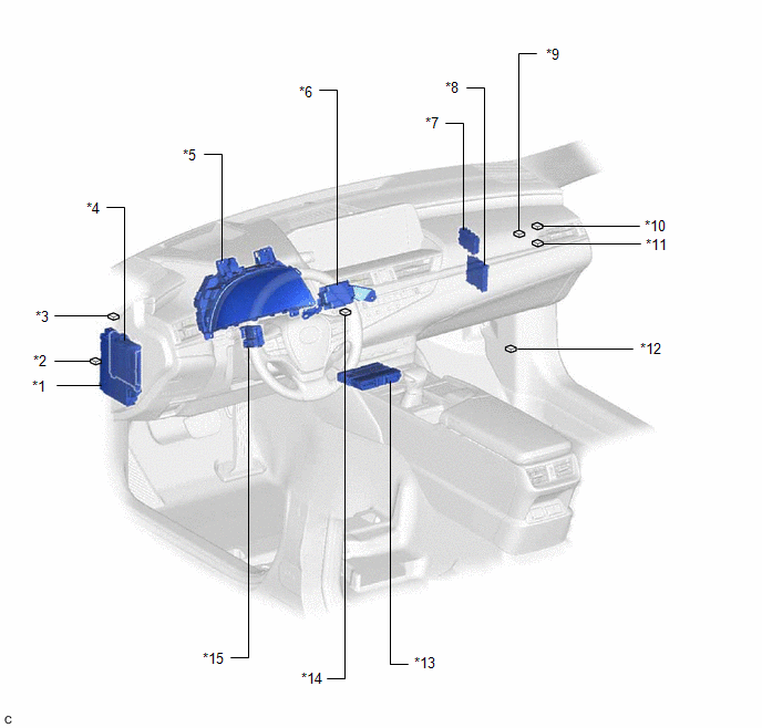
| *1 | INSTRUMENT PANEL JUNCTION BLOCK ASSEMBLY | *2 | NO. 2 CAN JUNCTION CONNECTOR |
| *3 | NO. 2 JUNCTION CONNECTOR | *4 | MAIN BODY ECU (MULTIPLEX NETWORK BODY ECU) |
| *5 | COMBINATION METER ASSEMBLY | *6 | STEREO COMPONENT EQUALIZER ASSEMBLY |
| *7 | CENTRAL GATEWAY ECU (NETWORK GATEWAY ECU) | *8 | CLEARANCE WARNING ECU ASSEMBLY (w/ Parking Support Alert System) |
| *9 | NO. 4 CAN JUNCTION CONNECTOR | *10 | NO. 1 CAN JUNCTION CONNECTOR |
| *11 | NO. 1 JUNCTION CONNECTOR | *12 | OPTION CONNECTOR (BUS BUFFER ECU) (w/ CAN Compatible Optional Devices) |
| *13 | DCM (TELEMATICS TRANSCEIVER) (w/ Telematics Transceiver) | *14 | NO. 5 CAN JUNCTION CONNECTOR |
| *15 | MULTIPLEX TILT AND TELESCOPIC ECU (w/ Power Tilt and Power Telescopic System) | - | - |
READ NEXT:
 Precaution
PRECAUTION NOTICE FOR INITIALIZATION NOTICE: When disconnecting the cable from the negative (-) auxiliary battery terminal, initialize the following systems after the cable is reconnected. System
Tire Pressure Monitor ECU Communication Stop Mode
DESCRIPTION Detection Item Symptom Trouble Area Tire Pressure Monitor ECU Communication Stop Mode Any of the following conditions are met:
Communication stop for "Tire Pressure" is ind
SEE MORE:
How To Proceed With Troubleshooting
CAUTION / NOTICE / HINT HINT:
Use the following procedure to troubleshoot the blind spot monitor system.
*: Use the Techstream.
PROCEDURE 1. VEHICLE BROUGHT TO WORKSHOP
NEXT 2. CUSTOMER PROBLEM ANALYSIS HINT: If there are any scratches or impact marks on th
Evaporative Emission System Leak Detection Reference Orifice Low Flow (P043E00,P043F00,P24007E,P24007F,P24187E)
DTC SUMMARY DTC No. Detection Item DTC Detection Condition Trouble Area MIL Memory Note P043E00 Evaporative Emission System Leak Detection Reference Orifice Low Flow Reference orifice clogged during key-off EVAP monitor
Canister pump module
Wire harness or connector (ca
