Lexus ES: System Description
SYSTEM DESCRIPTION
FUNCTION OF COMPONENTS
(a) The parking support brake system consists of the following components:
| Component | Function |
|---|---|
| Clearance Warning ECU Assembly |
|
| Steering Pad Switch Assembly - Multi-information Switch | Enables, disables or cuts off the operation of the parking support brake system by transmitting the switch operation signal to the combination meter assembly. |
| hybrid vehicle control ECU | Sends the engine speed signal to the clearance warning ECU assembly via CAN communication. |
| Hybrid Vehicle Control ECU |
|
| Combination Meter Assembly - Multi-information Display - PKSB OFF Indicator - Meter buzzer |
|
| Headup Display (Meter Mirror Sub-assembly)*1 | Displays the control status of the parking support brake system based on the signals received from the clearance warning ECU assembly via CAN communication. |
| Stop Light Switch Assembly | Detects if the brake pedal is depressed and outputs a signal to the skid control ECU. |
| Skid Control ECU |
|
| Steering Sensor | Sends the steering angle signal to the clearance warning ECU assembly via CAN communication. |
| Airbag Sensor Assembly
| Sends the yaw rate and acceleration sensor signal to the clearance warning ECU assembly via CAN communication. |
| Sends the wheel speed signals to the skid control ECU. |
| Ultrasonic Sensor | Detects the distance between the vehicle and an obstacle. |
| No. 1 Clearance Warning Buzzer | Sounds upon receiving signals from the Clearance Warning ECU Assembly. |
| No. 2 Clearance Warning Buzzer | Sounds upon receiving signals from the Clearance Warning ECU Assembly. |
| Accelerator Pedal Sensor Assembly | Sends the accelerator pedal opening angle signal to the hybrid vehicle control ECU. |
| Main Body ECU (Multiplex Network Body ECU) | Sends the driver seat belt signal to the clearance warning ECU assembly. |
| Air Conditioning Amplifier Assembly | Sends the ambient temperature signal to the clearance warning ECU assembly. |
| Blind Spot Monitor Sensor (LH/RH)*2 | Sends blind spot monitor system status signals to the clearance warning ECU assembly via CAN communication. |
| RCTA Buzzer (Blind Spot Monitor Buzzer)*2 | Sounds based on a signal from the blind spot monitor sensor. |
| Rear Television Camera Assembly*3 |
|
- *1: w/ Headup Display System
- *2: w/ Blind spot monitor system
- *3: w/ Panoramic View Monitor System
OPERATION CONDITIONS (PARKING SUPPORT BRAKE SYSTEM)
(a) Driving torque restriction control
(1) Initiation Condition (When all of the following conditions are met, the driving torque restriction control is performed.)
- The parking support brake system is turned on.
- An static objects is detected by an ultrasonic sensor.
- The vehicle speed is 15 km/h (9 mph) or less.
- Collision is avoidable if emergency braking is performed by the driver.
(2) Cancellation Condition (When any of the following conditions are met, driving torque restriction control is cancelled.)
- The parking support brake system is turned off.
- No static objects is detected by the ultrasonic sensors.
- A possible collision is avoided.
(b) Brake Control
(1) Initiation Condition (When all of the following conditions are met, brake control is performed.)
- Driving torque restriction control is performed.
- A collision is likely even if emergency braking is performed by the driver.
(2) Cancellation Condition (When any of the following conditions are met, driving torque restriction control is cancelled.)
- The parking support brake system is turned off.
- The brake pedal is depressed after the vehicle is stopped by brake control.
- Approximately 2 seconds have elapsed since the vehicle was stopped by brake control.
- No static objects is detected by the ultrasonic sensors.
(c) Others
-
When brake control is performed, the parking support brake system turns off automatically. The parking support brake system turns on again when no static objectss are detected by the ultrasonic sensors, the shift lever is moved from D to R or is moved from R to D, the power switch is turned off and then turned on (IG), or by using the settings screen on the multi-information display. Parking support brake system operation
.png)
OPERATION CONDITIONS (REAR CROSS TRAFFIC AUTO BRAKE FUNCTION)
(a) Driving torque restriction control
(1) Initiation Condition (When all of the following conditions are met, the driving torque restriction control is performed.)
- The parking support brake system is turned on.
- The shift lever is in R.
- When a vehicle is approaching the right or left at the rear of the vehicle.
- The vehicle speed is 15 km/h (9 mph) or less.
- When a collision with an approaching vehicle is imminent
(2) Cancellation Condition (When any of the following conditions are met, driving torque restriction control is cancelled.)
- The parking support brake system is turned off.
- When the vehicle approaching the right or left at the rear of the vehicle is no longer detected.
- A possible collision is avoided.
(b) Brake Control
(1) Initiation Condition (When all of the following conditions are met, brake control is performed.)
- Driving torque restriction control is performed.
- A collision is likely even if emergency braking is performed by the driver.
(2) Cancellation Condition (When any of the following conditions are met, driving torque restriction control is cancelled.)
- The parking support brake system is turned off.
- The brake pedal is depressed after the vehicle is stopped by brake control.
- Approximately 2 seconds have elapsed since the vehicle was stopped by brake control.
- When the vehicle approaching the right or left at the rear of the vehicle is no longer detected.
(c) Others
-
When brake control is performed, the parking support brake system turns off automatically. The parking support brake system turns on again when no static objectss are detected by the ultrasonic sensors, the shift lever is moved from D to R or is moved from R to D, the power switch is turned off and then turned on (IG), or by using the settings screen on the multi-information display. Rear cross traffic auto brake function operation
.png)
OPERATION CONDITIONS (PARKING SUPPORT BRAKE [REAR PEDESTRIANS])
(a) Driving torque restriction control
(1) Initiation Condition (When all of the following conditions are met, the driving torque restriction control is performed.)
- The parking support brake system is turned on.
- The shift position is in R.
- The vehicle speed is 15 km/h (9 mph) or less.
- Possibility of collision with pedestrian behind vehicle.
(2) Cancellation Condition (When any of the following conditions are met, driving torque restriction control is canceled.)
- The parking support brake system is turned off.
- A possible collision is avoided.
- Pedestrians behind vehicle are no longer there.
(b) Brake Control
(1) Initiation Condition (When all of the following conditions are met, brake control is performed.)
- Driving torque restriction control is performed.
- A collision is likely even if emergency braking is performed by the driver.
(2) Cancellation Condition (When any of the following conditions are met, driving torque restriction control is canceled.)
- The parking support brake system is turned off.
- The brake pedal is depressed after the vehicle is stopped by brake control.
- Approximately 2 seconds have elapsed since the vehicle was stopped by brake control.
- Pedestrians behind vehicle are no longer there.
(c) Others
- When the system operates up to the brake control, the parking support brake system switch turns off automatically, and remains off until either the driver performs the parking support brake system switch on operation, the pedestrians to the rear of the vehicle disappear or the driver reverses the vehicle by 300 mm (11.8 in.) or more.
.png)
CASES OF UNNECESSARY PARKING SUPPORT BRAKE SYSTEM OPERATION
(a) In the following situations, the parking support brake system may operate even when there is no possibility of a collision:
(1) Environmental influence
-
There is an obstacle on the shoulder of the road (when the vehicle is driven in a narrow tunnel, on a narrow bridge or on a narrow road).
.png)
-
The vehicle is being driven on grass or a gravel road.
.png)
-
The vehicle is driven toward a banner or flag, a low-hanging branch or a boom barrier (such as those used at railroad cross, toll gates and parking lots).
.png)
HINT:
Even if the parking support brake system operates while on a railroad cross, brake control will be automatically be canceled after approximately 2 seconds. Brake control can also be canceled by depressing the brake pedal. After brake control is canceled, depress the accelerator pedal to drive out of the railroad cross.
-
The vehicle is close to other vehicles while being parallel parked.
.png)
-
The vehicle is being driven on a steep slope.
.png)
-
There are objects located lower than the ultrasonic sensors.
.png)
-
The vehicle is being driven on a narrow road.
.png)
- There is a rut or hole in the surface of the road.
- When the vehicle is driven on a metal cover (grating), such as those used for drainage ditches.
(2) Influence from the weather
.png)
- In severe weather such as fog, snow or a sandstorm.
- Foreign matter such as snow, ice or mud is attached to an ultrasonic sensor. (The system returns to normal when the foreign matter is removed.)
- When there is a downpour, or water is splashing on the vehicle.
- Water is covering an ultrasonic sensor due to a flooded road.
(3) Influence from other ultrasonic waves
- When ultrasonic waves are received from the horn or parking sonar system of another vehicle, a motorcycle engine, or the air brakes of a large vehicle.
- Electronic components such as a backlit license plate (especially fluorescent types), fog lights, a fender pole or a wireless antenna are installed near an ultrasonic sensor.
(4) Changes in the vehicle.
.png)
- The height of the vehicle has drastically changed due to loading (the nose tilts up or down).
- The vehicle is significantly tilted.
- An ultrasonic sensor is misaligned due to a collision, etc.
(5) Others
.png)
- The vehicle is being loaded onto a ship, truck or other transport vessel.
- The vehicle is being operated on a drum tester such as a speedometer tester, brake/speedometer combination tester or chassis dynamometer.
- When the vehicle is being towed.
CASES OF UNNECESSARY REAR CROSS TRAFFIC AUTO BRAKE FUNCTION OPERATION
(a) In the following situations, the rear cross traffic auto brake function may operate even when there is no possibility of a collision:
-
When a vehicle is travelling along a road that is located extremely close to a parking space.
.png)
-
When a vehicle is entering an adjacent parking space.
.png)
-
When an object is passing extremely close to the vehicle.
.png)
-
When there is a metal object behind the vehicle such as a guard rail, wall, traffic sign or parked vehicle that easily reflects radio waves.
.png)
CASES OF UNNECESSARY PARKING SUPPORT BRAKE (REAR PEDESTRIANS)
(a) Situations in which pedestrians cannot be detected normally.
-
Solid objects (pillars, pylons, fences, parked vehicles, etc.)
.png)
-
Moving objects (such as passing vehicles, motorcycles, etc.)
.png)
-
Moving objects (such as flags, exhaust gas, large drops of rain, large snowflakes, rainwater on roads, etc.)
.png)
-
Patterns on roads (white lines, pedestrian crossings, stones, streetcar rails, repaired areas, fallen leaves, gravel, etc.)
.png)
Surrounding objects reflected off puddles or wet road surfaces.
-
Shadows.
.png)
-
Driving onto an area with a difference in height.
.png)
Grating, ditches and gutters.
Sides of roads and steps.
-
The vehicle is extremely tilted (loaded, suddenly braking, etc.).
A lowered suspension or tire with a different diameter than a genuine tire, etc. is installed.
There are changes in gradient.
.png)
-
The camera is dirty (dirty, snow-melting agents, etc.).
.png)
Water drops are moving over the camera lens.
(1) Others
- An aftermarket accessory (backlit license plate, fog light, etc.) is installed near the rear camera.
- An aftermarket protective part is installed to the rear bumper (bumper trim, etc.).
- The axis of the camera is misaligned (due to reinstallation, collision, etc.).
- A towing hook is installed.
MULTI-INFORMATION DISPLAY AND HEADUP DISPLAY (w/ Headup Display System)
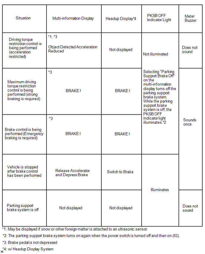
(a) Parking support brake system display
- The parking support brake system uses the multi-information display in the combination meter assembly, the meter mirror sub-assembly* and PKSB OFF indicator light to indicate the operation status of the system.
(b) Parking support brake system operation status display
- When the operation conditions are met, the clearance warning ECU assembly sends display or illumination request signals to the combination meter assembly, meter mirror sub-assembly* and PKSB OFF indicator light. The clearance warning ECU assembly also sends buzzer sound request signals to the combination meter assembly.
- *: w/ Headup Display System
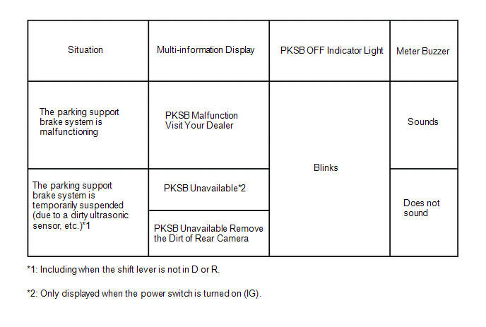
(c) Parking support brake system parking support brake system warning display
- When operation of the parking support brake system is temporarily suspended due to a malfunction or dirty ultrasonic sensor, a message is displayed on the multi-information display in the combination meter assembly, the PKSB OFF indicator light blinks and the buzzer sounds.
(d) Parking support brake system off display
- When the parking support brake system is off, the PKSB OFF indicator light illuminates.
.png)
| *a | PKSB OFF Indicator |
READ NEXT:
 System Diagram
SYSTEM DIAGRAM w/ Blind Spot Monitor System w/ Panoramic View Monitor System
Terminals Of Ecu
TERMINALS OF ECU CLEARANCE WARNING ECU ASSEMBLY (a) Disconnect the N41 clearance warning ECU assembly connector. (b) Measure the voltage and resistance on the wire harness side connector according to
Terminals Of Ecu
TERMINALS OF ECU CLEARANCE WARNING ECU ASSEMBLY (a) Disconnect the N41 clearance warning ECU assembly connector. (b) Measure the voltage and resistance on the wire harness side connector according to
SEE MORE:
High Voltage Power Resource Circuit Consumption Circuit Short (P1C8149,P1C8249)
DTC SUMMARY MALFUNCTION DESCRIPTION The hybrid vehicle control ECU monitors the high-voltage wiring between the HV battery and inverter with converter assembly and detects a short circuit malfunction or high-voltage system operation malfunction. The cause of this malfunction may be one of the follow
Telematics Transceiver Disconnected (B15DB)
DESCRIPTION If the radio receiver assembly cannot detect the DCM (telematics transceiver) for a certain period of time (90 seconds) after the engine switch is turned on (ACC) and the radio receiver assembly confirms that the information is missing by checking past DCM (telematics transceiver) recogn
