Lexus ES: Removal
REMOVAL
CAUTION / NOTICE / HINT
HINT:
- Use the same procedure for the RH side and LH side.
- The following procedure is for the LH side.
PROCEDURE
1. REMOVE OUTER MIRROR
(a) Apply protective tape to the areas shown in the illustration.
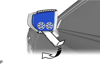
.png) | Protective Tape |
.png) | Move in this Direction |
(b) Push the upper part of the mirror surface and tilt it.
(c) Using a moulding remover, disengage the 2 claws on the lower part of the outer mirror as shown in the illustration.
NOTICE:
Do not push the outer mirror with excessive force. Doing so may cause the actuator to come off or break the mirror surface.
(d) Push the lower part of the mirror surface and tilt it.
(e) w/o Blind Spot Monitor System:
(1) Using a moulding remover, disengage the 2 claws on the upper part of the outer mirror as shown in the illustration.
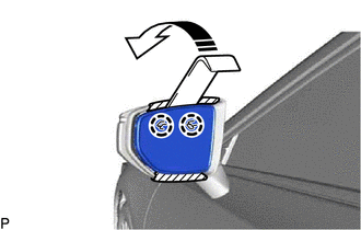
| | Move in this Direction |
NOTICE:
Do not push the outer mirror with excessive force. Doing so may cause the actuator to come off or break the mirror surface.
| (2) Disengage the clamp. |
|
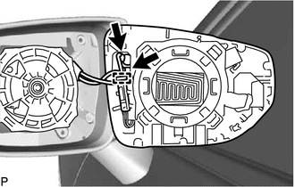
(3) Disconnect the 2 connectors.
| (4) Disengage the clamp. |
|
(5) Disengage the claw.
(6) Disconnect the connector to remove the outer mirror.
(f) w/ Blind Spot Monitor System:
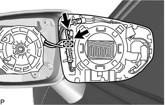
(1) Using a moulding remover, disengage the 2 claws on the upper part of the outer mirror as shown in the illustration.

| | Move in this Direction |
NOTICE:
Do not push the outer mirror with excessive force. Doing so may cause the actuator to come off or break the mirror surface.
| (2) Disengage the clamp. |
|
(3) Disconnect the 2 connectors.
| (4) Disengage the clamp. |
|
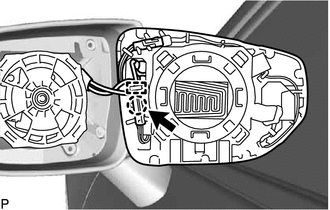
(5) Disengage the claw.
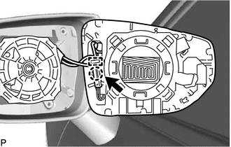
(6) Disconnect the connector.
| (7) Disengage the clamp. |
|
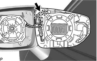
(8) Disengage the claw.
(9) Disconnect the connector to remove the outer mirror.
READ NEXT:
 Inspection
INSPECTION PROCEDURE 1. INSPECT OUTER MIRROR RH (a) Check the outer mirror heater operation. (1) Measure the resistance according to the value(s) in the table below. Standard Resistance: Tester
Installation
INSTALLATION CAUTION / NOTICE / HINT HINT:
Use the same procedure for the RH side and LH side.
The following procedure is for the LH side.
PROCEDURE 1. INSTALL OUTER MIRROR (a) w/o Blind Spot
SEE MORE:
Generator Inverter Actuator Stuck Open (P0A7A72)
DTC SUMMARY MALFUNCTION DESCRIPTION This DTC indicates that current does not flow as commanded due to a generator output circuit malfunction. The cause of this malfunction may be one of the following: Internal inverter malfunction
Inverter with converter assembly internal circuit malfunction
On-vehicle Inspection
ON-VEHICLE INSPECTION PROCEDURE 1. INSPECT CAM TIMING OIL CONTROL SOLENOID ASSEMBLY (a) Connect the Techstream to the DLC3. (b) Turn the power switch on (IG). (c) Turn the Techstream on. (d) Put the engine in Inspection Mode (Maintenance Mode). Powertrain > Hybrid Control > Utility Tester D
