
Lexus ES: Installation
Lexus ES (XZ10) Service Manual / Vehicle Exterior / Mirror (ext) / Outer Rear View Mirror Glass / Installation
INSTALLATION
CAUTION / NOTICE / HINT
HINT:
- Use the same procedure for the RH side and LH side.
- The following procedure is for the LH side.
PROCEDURE
1. INSTALL OUTER MIRROR
(a) w/o Blind Spot Monitor System:
(1) Connect the connector.
(2) Engage the claw.
(3) Engage the clamp.
(4) Connect the 2 connectors.
(5) Engage the clamp.
| (6) Engage the 4 claws to install the outer mirror. NOTICE: Do not push the outer mirror with excessive force. Doing so may break the mirror surface. |
|
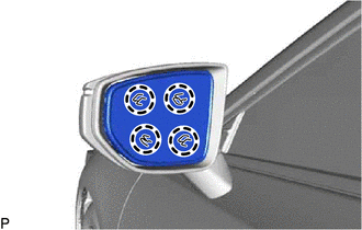
(b) w/ Blind Spot Monitor System:
(1) Connect the connector.
(2) Engage the claw.
(3) Engage the clamp.
(4) Connect the connector.
(5) Engage the claw.
(6) Engage the clamp.
(7) Connect the 2 connectors.
(8) Engage the clamp.
| (9) Engage the 4 claws to install the outer mirror. NOTICE: Do not push the outer mirror with excessive force. Doing so may break the mirror surface. |
|
READ NEXT:
 Precaution
PRECAUTION PRECAUTION FOR DISCONNECTING CABLE FROM NEGATIVE BATTERY TERMINAL NOTICE: When disconnecting the cable from the negative (-) battery terminal, initialize the following systems after the cab
Parts Location
PARTS LOCATION ILLUSTRATION *1 OUTER REAR VIEW MIRROR ASSEMBLY (DRIVER DOOR) *2 OUTER REAR VIEW MIRROR ASSEMBLY (FRONT PASSENGER DOOR) *3 OUTER MIRROR (DRIVER DOOR) *4 OUTER MIRROR
SEE MORE:
Installation
INSTALLATION PROCEDURE 1. INSTALL FUEL PUMP CONTROL ECU BRACKET (a) Install the fuel pump control ECU bracket to the fuel pump control ECU with the 2 bolts. Torque: 4.5 N·m {46 kgf·cm, 40 in·lbf} 2. INSTALL FUEL PUMP CONTROL ECU (a) Install the fuel pump control ECU to the vehicle body with the
Parts Location
PARTS LOCATION ILLUSTRATION *1 ROOF ANTENNA ASSEMBLY - GPS - Telephone Main *2 CERTIFICATION ECU (SMART KEY ECU ASSEMBLY) *3 NAVIGATION ANTENNA ASSEMBLY - Telephone Sub *4 MAIN BODY ECU (MULTIPLEX NETWORK BODY ECU) *5 INSTRUMENT PANEL JUNCTION BLOCK ASSEMBLY - DCM FUSE - EC
© 2016-2026 Copyright www.lexguide.net
