Lexus ES: Removal
REMOVAL
CAUTION / NOTICE / HINT
HINT:
- Use the same procedure for the RH side and LH side.
- The following procedure is for the LH side.
PROCEDURE
1. REMOVE NO. 2 ROCKER PANEL MOULDING PROTECTOR
Click here .gif)
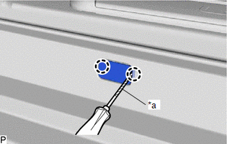
2. REMOVE ROCKER PANEL MOULDING COVER
| (a) Using a screwdriver with its tip wrapped with protective tape, disengage the 2 claws to remove the rocker panel moulding cover. HINT: Use the same procedure for the other rocker panel moulding cover. |
|
3. REMOVE BODY ROCKER PANEL MOULDING ASSEMBLY
(a) Apply protective tape around the body rocker panel moulding assembly and doors as shown in the illustration.
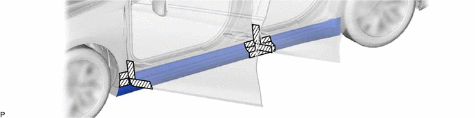
.png) | Protective Tape | - | - |
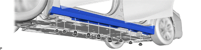
(b) Remove the 9 clips.
(c) Remove the 6 screws.
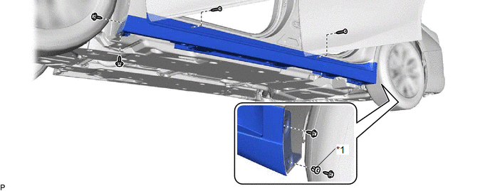
| *1 | Grommet | - | - |
(d) Remove the grommet
(e) Disengage the 9 clips to remove the body rocker panel moulding assembly as shown in the illustration.
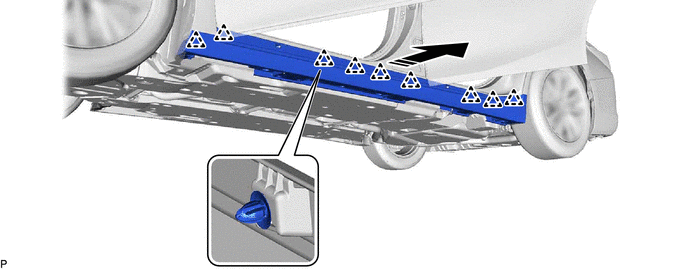
.png) | Remove in this Direction | - | - |
READ NEXT:
 Disassembly
DISASSEMBLY PROCEDURE 1. REMOVE NO. 4 ROCKER PANEL MOULDING PROTECTOR (a) Remove the No. 4 rocker panel moulding protector. 2. REMOVE NO. 5 ROCKER PANEL MOULDING PROTECTOR (a) Remove
Reassembly
REASSEMBLY PROCEDURE 1. INSTALL NO. 5 ROCKER PANEL MOULDING PROTECTOR HINT: When installing the No. 5 rocker panel moulding protector, heat the body rocker panel moulding assembly using a heat light.
Installation
INSTALLATION CAUTION / NOTICE / HINT HINT:
Use the same procedure for the RH side and LH side.
The following procedure is for the LH side.
PROCEDURE 1. INSTALL BODY ROCKER PANEL MOULDING ASSEM
SEE MORE:
Engine Oil Pressure Sensor/Switch "A" Signal Stuck High (P052024,P05202A)
DESCRIPTION Refer to DTC P052012. Click here DTC No. Detection Item DTC Detection Condition Trouble Area MIL Memory Note P052024 Engine Oil Pressure Sensor/Switch "A" Signal Stuck High The oil pressure sensor output voltage is higher than the threshold value (1 trip detectio
Propeller Shaft System
Problem Symptoms TablePROBLEM SYMPTOMS TABLE HINT: Use the table below to help determine the cause of problem symptoms. If multiple suspected areas are listed, the potential causes of the symptoms are listed in order of probability in the "Suspected Area" column of the table. Check each symptom by
© 2016-2026 Copyright www.lexguide.net
