
Lexus ES: Installation
Lexus ES (XZ10) Service Manual / Audio & Visual & Telematics / Audio / Video / Microphone / Installation
INSTALLATION
PROCEDURE
1. INSTALL TELEPHONE MICROPHONE ASSEMBLY
(a) Connect the connector.
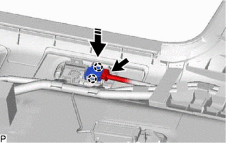
.png) | Install in this Direction |
(b) Engage the 2 claws to install the telephone microphone assembly as shown in the illustration.
2. INSTALL ROOF HEADLINING ASSEMBLY
Click here .gif)
READ NEXT:
 Removal
REMOVAL CAUTION / NOTICE / HINT The necessary procedures (adjustment, calibration, initialization, or registration) that must be performed after parts are removed and installed, or replaced during tel
Components
COMPONENTS ILLUSTRATION *A for HV Model *B for Gasoline Model *1 RADIO SETTING CONDENSER *2 REAR DOOR SCUFF PLATE LH *3 REAR SEAT SIDE GARNISH LH *4 ROOF SIDE INNER GARNI
SEE MORE:
Components
COMPONENTS ILLUSTRATION *1 LOWER STEERING COLUMN COVER SUB-ASSEMBLY *2 TURN SIGNAL SWITCH *3 UPPER STEERING COLUMN COVER - -
Dcm Activation
DCM ACTIVATION HINT: If the DCM (telematics transceiver) has been replaced, it is necessary to perform the Register Vehicle Information procedure. DCM ACTIVATION (a) Connect the Techstream to the DLC3. (b) Turn the engine switch on (IG). (c) Turn the Techstream on. (d) Choose "Telematics" from the S
© 2016-2026 Copyright www.lexguide.net
