Lexus ES: Removal
REMOVAL
CAUTION / NOTICE / HINT
The necessary procedures (adjustment, calibration, initialization or registration) that must be performed after parts are removed and installed, or replaced during hybrid battery terminal block removal/installation are shown below.
Necessary Procedures After Parts Removed/Installed/Replaced| Replaced Part or Performed Procedure | Necessary Procedure | Effect/Inoperative Function when Necessary Procedure not Performed | Link |
|---|---|---|---|
|
*: When performing learning using the Techstream.
Click here | |||
| Auxiliary battery terminal is disconnected/reconnected | Perform steering sensor zero point calibration | Lane Control System | |
| Pre-collision System | |||
| Parking Support Brake System* | |||
| Lighting System | |||
| Memorize steering angle neutral point | Parking assist monitor system | | |
| Panoramic view monitor system | | ||
| Initialize power trunk lid system | Power Trunk Lid System | | |
| Replacement of hybrid battery terminal block | High voltage fuse accumulated load history reset | DTCs are stored | |
CAUTION:
-
Orange wire harnesses and connectors indicate high-voltage circuits. To prevent electric shock, always follow the procedure described in the repair manual.
.png)
Click here
.gif)
-
To prevent electric shock, wear insulated gloves when working on wire harnesses and components of the high voltage system.
.png)
NOTICE:
- After the power switch is turned off, the radio receiver assembly records various types of memory and settings. As a result, after turning the power switch off, make sure to wait at least 85 seconds before disconnecting the cable from the negative (-) auxiliary battery terminal. (for Audio and Visual System)
- After the power switch is turned off, the radio receiver assembly records various types of memory and settings. As a result, after turning the power switch off, make sure to wait at least 85 seconds before disconnecting the cable from the negative (-) auxiliary battery terminal. (for Navigation System)
PROCEDURE
1. REMOVE HV BATTERY
Click here
2. REMOVE UPPER HV BATTERY COVER SUB-ASSEMBLY
Click here
3. REMOVE NO. 1 HV BATTERY SHIELD PANEL
Click here
4. REMOVE HYBRID BATTERY TERMINAL BLOCK
CAUTION:
Be sure to wear insulated gloves and protective goggles.
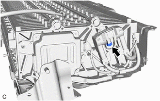
| (a) Remove the bolt to separate the hybrid battery terminal block from the HV battery. |
|
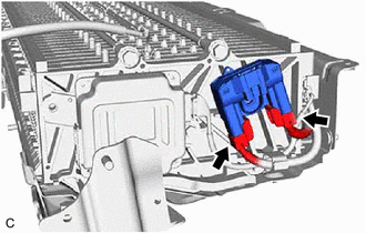
| (b) Disconnect the 2 hybrid battery terminal block connectors to remove the hybrid battery terminal block. NOTICE: Insulate the disconnected high-voltage connectors with insulating tape. |
|
READ NEXT:
 Inspection
INSPECTION PROCEDURE 1. INSPECT HYBRID BATTERY TERMINAL BLOCK (a) Measure the resistance according to the value(s) in the table below. Standard Resistance: Tester Connection Condition Speci
Installation
INSTALLATION PROCEDURE 1. INSTALL HYBRID BATTERY TERMINAL BLOCK CAUTION: Be sure to wear insulated gloves and protective goggles. (a) Connect the 2 hybrid battery terminal block connectors. NOTICE: Ma
SEE MORE:
Engine compartment
Components
Fuse boxes
Engine oil filler cap
Engine oil level dipstick
Brake fluid reservoir
Radiator
Electric cooling fan
Condenser
Power control unit coolant reservoir
Engine coolant reservoir
Washer fluid tank
Checking and adding the engine
oil
With the engine at op
Installation
INSTALLATION PROCEDURE 1. INSTALL MASS AIR FLOW METER SUB-ASSEMBLY HINT: Perform "Inspection After Repair" after replacing the mass air flow meter sub-assembly. Click here (a) Install the mass air flow meter sub-assembly to the air cleaner cap sub-assembly with the 2 screws. NOTICE:
If the mas
