Lexus ES: Removal
REMOVAL
CAUTION / NOTICE / HINT
The necessary procedures (adjustment, calibration, initialization or registration) that must be performed after parts are removed and installed, or replaced during port fuel injector assembly removal/installation are shown below.
Necessary Procedures After Parts Removed/Installed/Replaced| Replaced Part or Performed Procedure | Necessary Procedure | Effect/Inoperative Function when Necessary Procedure not Performed | Link |
|---|---|---|---|
|
*: When performing learning using the Techstream.
Click here | |||
| Auxiliary battery terminal is disconnected/reconnected | Perform steering sensor zero point calibration | Lane Control System (for HV Model) | |
| Pre-collision System (for HV Model) | |||
| Parking Support Brake System (for HV Model)* | |||
| Lighting System (for HV Model) | |||
| Memorize steering angle neutral point | Parking Assist Monitor System (for HV Model) | | |
| Panoramic View Monitor System (for HV Model) | | ||
| Initialize power trunk lid system | Power Trunk Lid System (for HV Model) | | |
| Inspection after repair |
| |
CAUTION:
-
Never perform work on fuel system components near any possible ignition sources.
.png)
- Vaporized fuel could ignite, resulting in a serious accident.
-
Do not perform work on fuel system components without first disconnecting the cable from the negative (-) auxiliary battery terminal.
.png)
- Sparks could cause vaporized fuel to ignite, resulting in a serious accident.
-
To prevent serious injury due to fuel spray from the high-pressure fuel lines, always discharge fuel system pressure before removing any fuel system components.
.png)
NOTICE:
- After the power switch is turned off, the radio receiver assembly records various types of memory and settings. As a result, after turning the power switch off, make sure to wait at least 85 seconds before disconnecting the cable from the negative (-) auxiliary battery terminal. (for Audio and Visual System)
- After the power switch is turned off, the radio receiver assembly records various types of memory and settings. As a result, after turning the power switch off, make sure to wait at least 85 seconds before disconnecting the cable from the negative (-) auxiliary battery terminal. (for Navigation System)
-
This procedure includes the removal of small-head bolts. Refer to Small-Head Bolts of Basic Repair Hint to identify the small-head bolts.
Click here
.gif)
PROCEDURE
1. PRECAUTION
NOTICE:
After turning the power switch off, waiting time may be required before disconnecting the cable from the negative (-) auxiliary battery terminal. Therefore, make sure to read the disconnecting the cable from the negative (-) auxiliary battery terminal notices before proceeding with work.
2. DISCHARGE FUEL SYSTEM PRESSURE
Click here
3. DISCONNECT CABLE FROM NEGATIVE AUXILIARY BATTERY TERMINAL
Click here
4. REMOVE THROTTLE BODY WITH MOTOR ASSEMBLY
Click here
5. REMOVE EGR VALVE ASSEMBLY
Click here
6. REMOVE NO. 2 WATER BY-PASS PIPE
Click here
7. DISCONNECT FUEL TUBE SUB-ASSEMBLY
| (a) Remove the fuel pipe clamp from the fuel tube connector. |
|
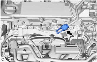
| (b) Disconnect the fuel tube sub-assembly from the fuel pump assembly and fuel delivery pipe sub-assembly. Click here |
|
.png)
8. REMOVE NO. 1 FUEL PIPE SUB-ASSEMBLY
CAUTION:
To prevent serious injury due to fuel spray from the high-pressure fuel lines, always discharge fuel system pressure before removing any fuel system components.
| (a) Disconnect the ignition coil connector. |
|
.png)
(b) for EGR Valve Bracket Connection Type:
| (1) Using a 17 mm union nut wrench, loosen the 2 union nuts of the No. 1 fuel pipe sub-assembly. |
|
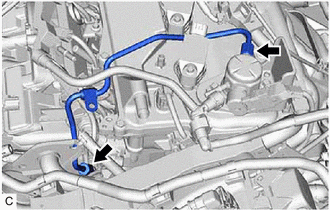
(c) for Cylinder Head Cover Sub-assembly Connection Type:
(1) Using a 17 mm union nut wrench, loosen the 2 union nuts of the No. 1 fuel pipe sub-assembly.
.png)
.png) | Union Nut |
.png) | Bolt |
(2) Using an 8 mm socket wrench, remove the bolt.
| (d) Loosen the 2 bolts of the fuel pump assembly. |
|
.png)
(e) Remove the No. 1 fuel pipe sub-assembly from the fuel delivery pipe and fuel pump assembly.
9. REMOVE FUEL PUMP ASSEMBLY
Click here
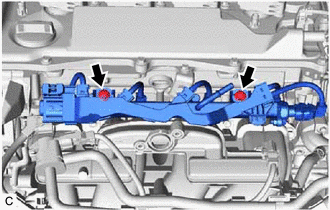
10. REMOVE FUEL DELIVERY PIPE SUB-ASSEMBLY
| (a) Disconnect the No. 5 engine wire connector. |
|
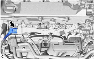
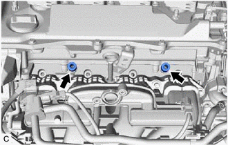
| (b) Remove the 2 bolts and fuel delivery pipe sub-assembly with the 4 port fuel injector assemblies from the cylinder head sub-assembly. NOTICE: Be careful not to drop the port fuel injector assemblies when removing the fuel delivery pipe sub-assembly. |
|
11. REMOVE NO. 1 DELIVERY PIPE SPACER
| (a) Remove the 2 No. 1 delivery pipe spacers from the cylinder head sub-assembly. |
|
12. REMOVE INJECTOR VIBRATION INSULATOR
| (a) Remove the 4 injector vibration insulators from the cylinder head sub-assembly. |
|
13. REMOVE NO. 5 ENGINE WIRE
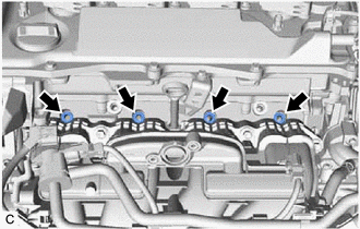
| (a) Disconnect the 4 port fuel injector assembly connectors and No. 2 fuel pressure sensor connector. |
|
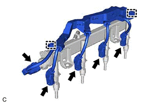
(b) Disengage the 2 clamps to remove the No. 5 engine wire from the fuel delivery pipe sub-assembly.
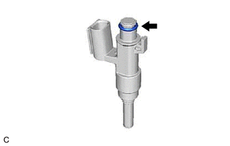
14. REMOVE PORT FUEL INJECTOR ASSEMBLY
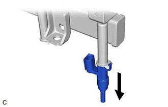
| (a) Pull the 4 port fuel injector assemblies out of the fuel delivery pipe sub-assembly. |
|
| (b) Remove the O-ring from each port fuel injector assembly. |
|
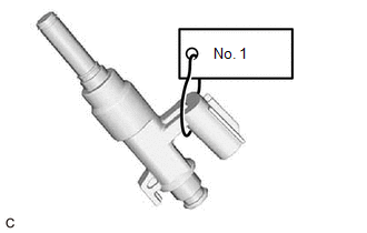
| (c) Attach a tag or label with the corresponding cylinder number to each port fuel injector assembly so that they can be installed to their original locations. NOTICE: Cover the port fuel injector assemblies with plastic bags to prevent damage and contamination. |
|
READ NEXT:
 Inspection
INSPECTION PROCEDURE 1. INSPECT PORT FUEL INJECTOR ASSEMBLY (a) Check the resistance. (1) Measure the resistance according to the value(s) in the table below. Standard Resistance: Tester Connec
Installation
INSTALLATION CAUTION / NOTICE / HINT NOTICE: This procedure includes the installation of small-head bolts. Refer to Small-Head Bolts of Basic Repair Hint to identify the small-head bolts. Click here
SEE MORE:
Transmission Fluid Temperature Sensor "C" Voltage Out of Range (P274A1C,P274A1F)
DTC SUMMARY MALFUNCTION DESCRIPTION These DTCs are stored when the transmission fluid temperature sensor output is abnormal. The cause of this malfunction may be one of the following: Transmission fluid temperature sensor malfunction
Internal transmission fluid temperature sensor malfunction
Op
Disassembly
DISASSEMBLY CAUTION / NOTICE / HINT CAUTION: If the rear disc brake cylinder assembly has been disassembled, perform air bleeding for the rear disc brake cylinder assembly. for Gasoline Model: Click here for HV Model: Click here NOTICE:
Make sure not to scratch, damage or apply excessive forc
