Lexus ES: Transmission Fluid Temperature Sensor "C" Voltage Out of Range (P274A1C,P274A1F)
DTC SUMMARY
MALFUNCTION DESCRIPTION
These DTCs are stored when the transmission fluid temperature sensor output is abnormal. The cause of this malfunction may be one of the following:
- Internal transmission fluid temperature sensor malfunction
- Open or short in transmission fluid temperature sensor
- The connectors are not connected properly
- Foreign matter or water on the connector terminals
- Open or short in wire harness
DESCRIPTION
Refer to the description for DTC P274A11.
Click here .gif)
| DTC No. | Detection Item | DTC Detection Condition | Trouble Area | MIL | Warning Indicate |
|---|---|---|---|---|---|
| P274A1C | Transmission Fluid Temperature Sensor "C" Voltage Out of Range | After a long soak, the value of the transmission fluid temperature sensor is different from the value of the other temperature sensors. (2 trip detection logic) |
| Comes on | Master Warning Light: Comes on |
| P274A1F | Transmission Fluid Temperature Sensor "C" Circuit Intermittent | Sudden change in transmission fluid temperature sensor output or hunting: Unusual sudden change in transmission fluid temperature sensor output occurs and offset condition continues for a certain period of time, or unusual change in transmission fluid temperature sensor output occurs repeatedly. (1 trip detection logic) |
| Comes on | Master Warning Light: Comes on |
| DTC No. | Data List |
|---|---|
| P274A1C |
|
| P274A1F | Transaxle Oil Temperature |
MONITOR DESCRIPTION
If the hybrid vehicle control ECU detects a malfunction of the transmission fluid temperature sensor, it will illuminate the MIL and store a DTC.
MONITOR STRATEGY
| Related DTCs | P274B (INF P274A1C): Transmission Fluid Temperature Sensor "C" Circuit Range/Performance P274E (INF P274A1F): Transmission Fluid Temperature Sensor "C" Circuit Intermittent |
| Required sensors/components | Transmission fluid temperature sensor |
| Frequency of operation | Continuous |
| Duration | TMC's intellectual property |
| MIL operation | 2 driving cycles / 1 driving cycle |
| Sequence of operation | None |
TYPICAL ENABLING CONDITIONS
| The monitor will run whenever the following DTCs are not stored | TMC's intellectual property |
| Other conditions belong to TMC's intellectual property | - |
TYPICAL MALFUNCTION THRESHOLDS
| TMC's intellectual property | - |
COMPONENT OPERATING RANGE
| Hybrid vehicle control ECU | DTC P274B (INF P274A1C) is not detected DTC P274E (INF P274A1F) is not detected |
CONFIRMATION DRIVING PATTERN
HINT:
-
After repair has been completed, clear the DTC and then check that the vehicle has returned to normal by performing the following All Readiness check procedure.
Click here
-
When clearing the permanent DTCs, refer to the "CLEAR PERMANENT DTC" procedure.
Click here
- Connect the Techstream to the DLC3.
- Turn the power switch on (IG) and turn the Techstream on.
- Clear the DTCs (even if no DTCs are stored, perform the clear DTC procedure).
- Turn the power switch off.
- Leave the vehicle as is for 5 hours or more and then check the values of the Data List items "Generator Temperature", "Motor Temperature" and "Transaxle Oil Temperature". [*1]
-
Turn the power switch on (IG) and turn the Techstream on. [*2]
HINT:
[*1] to [*2]: Normal judgment procedure.
The normal judgment procedure is used to complete DTC judgment and also used when clearing permanent DTCs.
- Enter the following menus: Powertrain / Hybrid Control / Utility / All Readiness.
-
Check the DTC judgment result.
HINT:
- If the judgment result shows NORMAL, the system is normal.
- If the judgment result shows ABNORMAL, the system has a malfunction.
- If the judgment result shows INCOMPLETE or N/A, perform the normal judgment procedure again.
- Connect the Techstream to the DLC3.
- Turn the power switch on (IG) and turn the Techstream on.
- Clear the DTCs (even if no DTCs are stored, perform the clear DTC procedure).
- Turn the power switch off and wait for 2 minutes or more.
- Turn the power switch on (IG) and turn the Techstream on.
-
With power switch on (IG) and wait for 5 seconds or more. [*1]
HINT:
[*1] : Normal judgment procedure.
The normal judgment procedure is used to complete DTC judgment and also used when clearing permanent DTCs.
- Enter the following menus: Powertrain / Hybrid Control / Utility / All Readiness.
-
Check the DTC judgment result.
HINT:
- If the judgment result shows NORMAL, the system is normal.
- If the judgment result shows ABNORMAL, the system has a malfunction.
- If the judgment result shows INCOMPLETE or N/A, perform the normal judgment procedure again.
WIRING DIAGRAM
Refer to the wiring diagram for DTC P274A11.
Click here
PROCEDURE
| 1. | CHECK DTC OUTPUT (ENGINE) |
(a) Connect the Techstream to the DLC3.
(b) Turn the power switch on (READY).
(c) Enter the following menus: Powertrain / Engine / Trouble Codes.
(d) Check for DTCs.
Powertrain > Engine > Trouble Codes| Result | Proceed to |
|---|---|
| No DTCs are output, or DTCs except the ones in the table below are also output. | A |
| Any of the following DTCs are also output. | B |
| Relevant DTC | |
|---|---|
| P261029 | ECM/PCM Engine Off Timer Performance Signal Invalid |
(e) Turn the power switch off.
| B | .gif) | GO TO DTC CHART (SFI SYSTEM) |
|
.gif)
| 2. | CHECK DTC OUTPUT (HYBRID CONTROL) |
(a) Connect the Techstream to the DLC3.
(b) Turn the power switch on (IG).
(c) Enter the following menus: Powertrain / Hybrid Control / Trouble Codes.
(d) Check for DTCs.
Powertrain > Hybrid Control > Trouble Codes| Result | Proceed to |
|---|---|
| No DTCs are output, or DTCs except the ones in the table below are also output | A |
| Any of the following DTCs are also output | B |
| Relevant DTC | |
|---|---|
| P274A11 | Transmission Fluid Temperature Sensor "C" Circuit Short to Ground |
| P274A15 | Transmission Fluid Temperature Sensor "C" Circuit Short to Auxiliary Battery or Open |
(e) Turn the power switch off.
| B | | GO TO DTC CHART (HYBRID CONTROL SYSTEM) |
|
| 3. | CHECK CONNECTOR CONNECTION CONDITION (HYBRID VEHICLE CONTROL ECU CONNECTOR) |
Click here
| Result | Proceed to |
|---|---|
| OK | A |
| NG (The connector is not connected securely.) | B |
| NG (The terminals are not making secure contact or are deformed, or water or foreign matter exists in the connector.) | C |
| B | | CONNECT SECURELY |
| C | | REPAIR OR REPLACE HARNESS OR CONNECTOR |
|
| 4. | CHECK HARNESS AND CONNECTOR (TRANSMISSION FLUID TEMPERATURE SENSOR - HYBRID VEHICLE CONTROL ECU) |
(a) Disconnect the A32 hybrid vehicle control ECU connector.
| (b) Measure the resistance according to the value(s) in the table below. Standard Resistance:
|
|
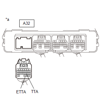
(c) Reconnect the A32 hybrid vehicle control ECU connector.
| NG | | GO TO STEP 9 |
|
| 5. | CHECK CONNECTOR CONNECTION CONDITION (INTERMEDIATE CONNECTOR) |
Click here
| Result | Proceed to |
|---|---|
| OK | A |
| NG (The connector is not connected securely.) | B |
| NG (The terminals are not making secure contact or are deformed, or water or foreign matter exists in the connector.) | C |
| B | | CONNECT SECURELY |
| C | | REPAIR OR REPLACE HARNESS OR CONNECTOR |
|
| 6. | CHECK HARNESS AND CONNECTOR (HYBRID VEHICLE CONTROL ECU - NO. 1 ENGINE ROOM RELAY BLOCK AND NO. 1 JUNCTION BLOCK ASSEMBLY) |
(a) Disconnect the CA4 No. 1 engine room relay block and No. 1 junction block assembly connector.
(b) Disconnect the A32 hybrid vehicle control ECU connector.
(c) Measure the resistance according to the value(s) in the table below.
HINT:
When performing the measurement, lightly jiggle the wire harness up and down and left and right and confirm that the resistance does not fluctuate.
Standard Resistance (Check for Open):
| Tester Connection | Condition | Specified Condition |
|---|---|---|
| CA4-2 (TTA) - A32-21 (TTA) | Power switch off | Below 1 Ω |
| CA4-3 (ETTA) - A32-31 (ETTA) | Power switch off | Below 1 Ω |
Standard Resistance (Check for Short):
| Tester Connection | Condition | Specified Condition |
|---|---|---|
| CA4-2 (TTA) or A32-21 (TTA) - Body ground and other terminals | Power switch off | 10 kΩ or higher |
| CA4-3 (ETTA) or A32-31 (ETTA) - Body ground and other terminals | Power switch off | 10 kΩ or higher |
(d) Reconnect the A32 hybrid vehicle control ECU connector.
(e) Reconnect the CA4 No. 1 engine room relay block and No. 1 junction block assembly connector.
| NG | | REPAIR OR REPLACE HARNESS OR CONNECTOR |
|
| 7. | CHECK CONNECTOR CONNECTION CONDITION (TRANSMISSION FLUID TEMPERATURE SENSOR CONNECTOR) |
Click here
| Result | Proceed to |
|---|---|
| OK | A |
| NG (The connector is not connected securely.) | B |
| NG (The terminals are not making secure contact or are deformed, or water or foreign matter exists in the connector.) | C |
| B | | CONNECT SECURELY |
| C | | REPAIR OR REPLACE HARNESS OR CONNECTOR |
|
| 8. | CHECK HARNESS AND CONNECTOR (NO. 1 ENGINE ROOM RELAY BLOCK AND NO. 1 JUNCTION BLOCK ASSEMBLY - TRANSMISSION FLUID TEMPERATURE SENSOR) |
(a) Disconnect the C91 transmission fluid temperature sensor connector.
(b) Disconnect the CA4 No. 1 engine room relay block and No. 1 junction block assembly connector.
(c) Measure the resistance according to the value(s) in the table below.
HINT:
When performing the measurement, lightly jiggle the wire harness up and down and left and right and confirm that the resistance does not fluctuate.
Standard Resistance (Check for Open):
| Tester Connection | Condition | Specified Condition |
|---|---|---|
| CA4-2 (TTA) - C91-3 (TTA) | Power switch off | Below 1 Ω |
| CA4-3 (ETTA) - C91-13 (ETTA) | Power switch off | Below 1 Ω |
Standard Resistance (Check for Short):
| Tester Connection | Condition | Specified Condition |
|---|---|---|
| CA4-2 (TTA) or C91-3 (TTA) - Body ground and other terminals | Power switch off | 10 kΩ or higher |
| CA4-3 (ETTA) or C91-13 (ETTA) - Body ground and other terminals | Power switch off | 10 kΩ or higher |
(d) Reconnect the CA4 No. 1 engine room relay block and No. 1 junction block assembly connector.
(e) Reconnect the C91 transmission fluid temperature sensor connector.
| OK | | REPLACE HYBRID VEHICLE TRANSAXLE ASSEMBLY |
| NG | | REPAIR OR REPLACE HARNESS OR CONNECTOR |
| 9. | INSPECT HYBRID VEHICLE TRANSAXLE ASSEMBLY (TRANSMISSION FLUID TEMPERATURE SENSOR) |
(a) Disconnect the CA4 No. 1 engine room relay block and No. 1 junction block assembly connector.
(b) Measure the resistance according to the value(s) in the table below.
Standard Resistance:
| Tester Connection | Condition | Specified Condition |
|---|---|---|
| CA4-2 (TTA) - CA4-3 (ETTA) | Power switch off | 1.393 to 75.8 kΩ |
(c) Reconnect the CA4 No. 1 engine room relay block and No. 1 junction block assembly connector.
| OK | | REPAIR OR REPLACE HARNESS OR CONNECTOR (HYBRID VEHICLE CONTROL ECU ASSEMBLY - NO. 1 ENGINE ROOM RELAY BLOCK AND NO. 1 JUNCTION BLOCK ASSEMBLY) |
|
| 10. | INSPECT HYBRID VEHICLE TRANSAXLE ASSEMBLY (TRANSMISSION FLUID TEMPERATURE SENSOR) |
Click here
| OK | | REPAIR OR REPLACE HARNESS OR CONNECTOR (NO. 1 ENGINE ROOM RELAY BLOCK AND NO. 1 JUNCTION BLOCK ASSEMBLY - TRANSMISSION FLUID TEMPERATURE SENSOR) |
| NG | | REPLACE HYBRID VEHICLE TRANSAXLE ASSEMBLY |
READ NEXT:
 High Voltage Power Resource Circuit Short during Pre-Charge (P300449)
DTC SUMMARY MALFUNCTION DESCRIPTION The hybrid vehicle control ECU monitors the high-voltage wiring between the HV battery and inverter with converter assembly and detects an open circuit malfunction.
Lost Communication with Airbag System Control Module Circuit Short to Ground (P310711)
DESCRIPTION The hybrid vehicle control ECU detects a problem in the collision signal line from the airbag ECU assembly and alerts the driver. DTC No. Detection Item DTC Detection Condition Tr
Lost Communication with Airbag System Control Module Circuit Short to Auxiliary Battery or Open (P310715)
DESCRIPTION Refer to the description for DTC P310711. Click here DTC No. Detection Item DTC Detection Condition Trouble Area MIL Warning Indicate P310715 Lost Communication with A
SEE MORE:
A Camshaft Position Actuator Bank 1 Circuit Open (P001013,P002013)
DESCRIPTION The Variable Valve Timing (VVT) system adjusts the intake valve timing to improve driveability. The engine oil pressure turns the VVT controller to adjust the valve timing. The cam timing oil control solenoid assembly operates according to signals received from the ECM to control the pos
Pressure Control Solenoid "C" Circuit Short to Ground or Open (P079514)
DESCRIPTION Refer to DTC P079512. Click here DTC No. Detection Item DTC Detection Condition Trouble Area MIL Memory Note P079514 Pressure Control Solenoid "C" Circuit Short to Ground or Open While the vehicle is being driven so that gear changes occur, a short to ground or o
