Lexus ES: Disassembly
DISASSEMBLY
CAUTION / NOTICE / HINT
CAUTION:
If the rear disc brake cylinder assembly has been disassembled, perform air bleeding for the rear disc brake cylinder assembly.
for Gasoline Model: Click here .gif)
for HV Model: Click here
NOTICE:
- Make sure not to scratch, damage or apply excessive force to any of the internal components of the rear disc brake cylinder.
- To prevent rusting on the inside of the rear disc brake cylinder, perform the rear disc brake piston removal and installation quickly.
- Do not clean the interior of the rear disc brake cylinder with brake cleaner.
- Do not remove any parts unless specifically instructed to do so, and only remove the parts indicated.
-
Make sure to enter pad replacement mode before removing the rear disc brake cylinder assembly.
for Gasoline Model: Click here
for HV Model: Click here
PROCEDURE
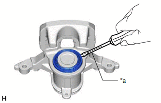
1. REMOVE CYLINDER BOOT
| (a) Using a screwdriver with its tip wrapped with protective tape, remove the cylinder boot from the rear disc brake cylinder. NOTICE: Do not damage the inner surface or cylinder boot groove of the rear disc brake cylinder. |
|
2. REMOVE REAR DISC BRAKE PISTON
| (a) Place a piece of cloth between the rear disc brake piston and rear disc brake cylinder. |
|
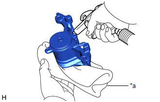
(b) Apply compressed air to remove the rear disc brake piston from the rear disc brake cylinder.
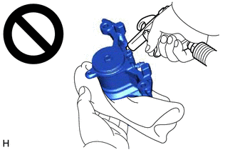
- Do not hold the rear disc brake cylinder with any part of your hand between the rear disc brake cylinder and rear disc brake piston.
- Do not place any part of your hand in front of the rear disc brake piston when using compressed air as a severe injury may result.
NOTICE:
Do not allow any brake fluid to spatter.
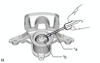
3. REMOVE PISTON SEAL
| (a) Using a screwdriver with its tip wrapped with protective tape, remove the piston seal from the rear disc brake cylinder. NOTICE:
|
|
4. REMOVE REAR DISC BRAKE BLEEDER PLUG CAP
(a) Remove the rear disc brake bleeder plug cap from the rear disc brake bleeder plug.
5. REMOVE REAR DISC BRAKE BLEEDER PLUG
(a) Remove the rear disc brake bleeder plug from the rear disc brake cylinder.
READ NEXT:
 Inspection
INSPECTION PROCEDURE 1. INSPECT BRAKE CYLINDER AND PISTON (a) Check the rear disc brake cylinder bore and rear disc brake piston for rust and scoring. If necessary, replace the rear disc brake cylinde
Inspection
INSPECTION PROCEDURE 1. INSPECT BRAKE CYLINDER AND PISTON (a) Check the rear disc brake cylinder bore and rear disc brake piston for rust and scoring. If necessary, replace the rear disc brake cylinde
Installation
INSTALLATION CAUTION / NOTICE / HINT NOTICE:
Immediately after installing the brake pads, the braking performance may be reduced. Always perform a road test in a safe place while paying attention t
SEE MORE:
Adjustment
ADJUSTMENT CAUTION / NOTICE / HINT *a Centering Bolt *b Standard Bolt HINT:
Use the same procedure for the RH side and LH side.
The following procedure is for the LH side.
Centering bolts are used to install the door hinges to the vehicle body and door. The door cannot be adjus
Components
COMPONENTS ILLUSTRATION *A w/o Panoramic View Monitor System *B w/ Panoramic View Monitor System *1 OUTER MIRROR *2 OUTER MIRROR COVER ASSEMBLY *3 OUTER MIRROR LOWER COVER *4 OUTER MIRROR UPPER COVER *5 SIDE TELEVISION CAMERA ASSEMBLY *6 VISOR COVER ASSEMBLY
