Lexus ES: Installation
INSTALLATION
CAUTION / NOTICE / HINT
NOTICE:
This procedure includes the installation of small-head bolts. Refer to Small-Head Bolts of Basic Repair Hint to identify the small-head bolts.
Click here .gif)
PROCEDURE
1. INSTALL PORT FUEL INJECTOR ASSEMBLY
HINT:
Perform "Inspection After Repair" after replacing a port fuel injector assembly.
Click here
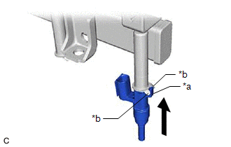
(a) Apply a light coat of spindle oil or gasoline to 4 new O-rings, and install one to each port fuel injector assembly.
NOTICE:
Check that there is no damage or foreign matter on the groove of the port fuel injector assembly when installing the O-ring to each port fuel injector assembly.
| (b) Install the 4 port fuel injector assemblies to the fuel delivery pipe sub-assembly. NOTICE:
|
|
2. INSTALL NO. 5 ENGINE WIRE
(a) Engage the 2 clamps to install the No. 5 engine wire to the fuel delivery pipe sub-assembly.
(b) Connect the 4 port fuel injector assembly connectors and No. 2 fuel pressure sensor connector.
3. INSTALL INJECTOR VIBRATION INSULATOR
(a) Install 4 new injector vibration insulators to the cylinder head sub-assembly.
4. INSTALL NO. 1 DELIVERY PIPE SPACER
| (a) Install the 2 No. 1 delivery pipe spacers to the cylinder head sub-assembly. NOTICE: Install the No. 1 delivery pipe spacers in the correct direction. |
|
5. INSTALL FUEL DELIVERY PIPE SUB-ASSEMBLY
(a) Place the fuel delivery pipe sub-assembly with the 4 port fuel injector assemblies onto the cylinder head sub-assembly.
NOTICE:
Be careful not to drop the port fuel injector assemblies when installing the fuel delivery pipe sub-assembly.
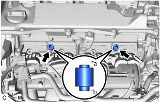
(b) Install the fuel delivery pipe sub-assembly with the port fuel injector assemblies with the 2 bolts.
Torque:
28.5 N·m {291 kgf·cm, 21 ft·lbf}
(c) Connect the No. 5 engine wire connector.
6. TEMPORARILY INSTALL FUEL (ENGINE ROOM SIDE) PUMP ASSEMBLY
Click here
7. TEMPORARILY INSTALL NO. 1 FUEL PIPE SUB-ASSEMBLY
NOTICE:
Do not damage the seals of the union nuts of the No. 1 fuel pipe sub-assembly.
(a) for Cylinder Head Cover Sub-assembly Connection Type:
(1) Temporarily install the bolt.
(b) Temporarily install the No. 1 fuel pipe sub-assembly to the fuel delivery pipe and tighten the union nut by hand.
(c) Temporarily install the No. 1 fuel pipe sub-assembly to the fuel pump assembly and tighten the union nut by hand.
8. INSTALL FUEL (ENGINE ROOM SIDE) PUMP ASSEMBLY
Click here
9. INSTALL NO. 1 FUEL PIPE SUB-ASSEMBLY
(a) for EGR Valve Bracket Connection Type:
| (1) Using a 17 mm union nut wrench, tighten the union nut on the fuel delivery pipe side of the No. 1 fuel pipe sub-assembly. Torque: Specified tightening torque : 35 N·m {357 kgf·cm, 26 ft·lbf} NOTICE: Do not adjust the torque in the loosening direction. HINT:
|
|
(2) Using a 17 mm union nut wrench, tighten the union nut on the fuel pump assembly side of the No. 1 fuel pipe sub-assembly.
Torque:
Specified tightening torque :
35 N·m {357 kgf·cm, 26 ft·lbf}
NOTICE:
Do not adjust the torque in the loosening direction.
HINT:
-
Calculate the torque wrench reading when changing the fulcrum length of the torque wrench.
Click here
- When using a 17 mm union nut wrench (fulcrum length of 30 mm (1.18 in.)) + torque wrench (fulcrum length of 180 mm (7.09 in.)): 30 N*m (306 kgf*cm, 22 ft.*lbf)
(b) for Cylinder Head Cover Sub-assembly Connection Type:
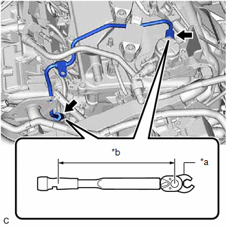
(1) Using a 17 mm union nut wrench, tighten the union nut on the fuel delivery pipe side of the No. 1 fuel pipe sub-assembly.
.png)
| *a | 17 mm Union Nut Wrench |
| *b | Torque Wrench Fulcrum Length |
.png) | Union Nut |
.png) | Bolt |
Torque:
Specified tightening torque :
35 N·m {357 kgf·cm, 26 ft·lbf}
NOTICE:
Do not adjust the torque in the loosening direction.
HINT:
-
Calculate the torque wrench reading when changing the fulcrum length of the torque wrench.
Click here
- When using a 17 mm union nut wrench (fulcrum length of 30 mm (1.18 in.)) + torque wrench (fulcrum length of 180 mm (7.09 in.)): 30 N*m (306 kgf*cm, 22 ft.*lbf)
(2) Using a 17 mm union nut wrench, tighten the union nut on the fuel pump assembly side of the No. 1 fuel pipe sub-assembly.
Torque:
Specified tightening torque :
35 N·m {357 kgf·cm, 26 ft·lbf}
NOTICE:
Do not adjust the torque in the loosening direction.
HINT:
-
Calculate the torque wrench reading when changing the fulcrum length of the torque wrench.
Click here
- When using a 17 mm union nut wrench (fulcrum length of 30 mm (1.18 in.)) + torque wrench (fulcrum length of 180 mm (7.09 in.)): 30 N*m (306 kgf*cm, 22 ft.*lbf)
(3) Using an 8 mm socket wrench, tighten the bolt.
Torque:
10 N·m {102 kgf·cm, 7 ft·lbf}
(c) Connect the ignition coil connector.
10. CONNECT FUEL TUBE SUB-ASSEMBLY
(a) Connect the fuel tube sub-assembly to the fuel pump assembly and fuel delivery pipe sub-assembly.
Click here
(b) Install the fuel pipe clamp to the fuel tube connector.
11. INSTALL NO. 2 WATER BY-PASS PIPE
Click here
12. INSTALL EGR VALVE ASSEMBLY
Click here
13. INSTALL THROTTLE BODY WITH MOTOR ASSEMBLY
Click here
14. CONNECT CABLE TO NEGATIVE AUXILIARY BATTERY TERMINAL
Click here
15. INSPECT FOR FUEL LEAK
Click here
16. PERFORM INITIALIZATION
(a) Perform "Inspection After Repair" after replacing a port fuel injector assembly.
Click here
READ NEXT:
 Components
COMPONENTS ILLUSTRATION *A for Type A - - *1 FUEL MAIN VALVE ASSEMBLY *2 FUEL SUCTION TUBE WITH PUMP AND GAUGE ASSEMBLY *3 O-RING - - ● Non-reusable part - -
Removal
REMOVAL CAUTION / NOTICE / HINT The necessary procedures (adjustment, calibration, initialization or registration) that must be performed after parts are removed and installed, or replaced during fuel
SEE MORE:
Grille Shutter Communication Stop Mode
DESCRIPTION Detection Item Symptom Trouble Area Grille Shutter Communication Stop Mode Any of the following conditions are met:
Communication stop for "Grill Shutter" is indicated on the "Communication Bus Check" screen of the Techstream.
Click here
Communication stop history fo
High Pressure Fuel Pump Circuit Open (P123513)
DESCRIPTION The high-pressure direct injection fuel system consists of a spill control valve, check valve, fuel relief valve, fuel pressure sensor, fuel pump assembly (for high pressure side) and direct fuel injector assemblies. The spill control valve adjusts the return volume of the high-pressure
