Lexus ES: Inspection
INSPECTION
PROCEDURE
1. INSPECT PORT FUEL INJECTOR ASSEMBLY
(a) Check the resistance.
| (1) Measure the resistance according to the value(s) in the table below. Standard Resistance:
If the result is not as specified, replace the port fuel injector assembly. |
|
.png)
(b) Check the operation.
CAUTION:
Perform the inspection in a well-ventilated area.
Do not perform the inspection near an open flame.
(1) Open the cover of the EFI fuel pipe clamp and remove the EFI fuel pipe clamp from the fuel tube connector.
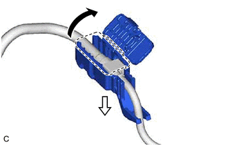
.png) | Open |
.png) | Pull |
| (2) Disconnect the fuel tube sub-assembly. Click here |
|
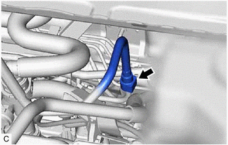
| (3) Connect SST (fuel tube connector) to SST (hose) with SST (hose band), and then connect them to the fuel pipe (vehicle side). SST: 09268-31015 09268-41500 09268-41700 95336-08070 NOTICE: Make sure the SST (fuel tube connector) O-rings are not damaged and are free of foreign matter as they are used to seal the connections between the fuel tube connector and fuel pipe. |
|
.png)
(4) Apply a light coat of gasoline to a new O-ring, and then install the O-ring to the port fuel injector assembly.
| (5) Connect SST (adapter) and SST (hose) to the port fuel injector assembly, and hold the port fuel injector assembly and union with SST (clamp). SST: 09268-31015 09268-41410 09268-41600 09268-41700 95336-08070 |
|
.png)
(6) Install a vinyl tube to the port fuel injector assembly.
CAUTION:
Install a suitable vinyl tube to the port fuel injector assembly to prevent fuel from spraying.
| (7) Tie SST (clamp) and SST (adapter) together with SST (tie band) as shown in the illustration. SST: 09268-31015 09268-41800 NOTICE:
HINT: When removing SST (tie band), disengage the lock. |
|
.png)
(8) Check that SST (clamp) and SST (adapter) cannot be easily separated.
(9) Set the port fuel injector assembly into a graduated cylinder.
(10) Connect the Techstream to the DLC3.
(11) Turn the power switch on (IG).
NOTICE:
Do not start the engine.
(12) Turn the Techstream on.
(13) Enter the following menus: Powertrain / Engine / Active Test / Activate the Circuit Relay.
Powertrain > Engine > Active Test| Tester Display |
|---|
| Activate the Circuit Relay |
| (14) Connect SST (EFI inspection wire K) to the port fuel injector assembly and auxiliary battery for 15 seconds, and measure the injection volume with the graduated cylinder. Test each port fuel injector assembly 2 or 3 times. SST: 09842-30110 Standard Injection Volume:
Difference between Each Port Fuel Injector Assembly: 14 cc (0.9 cu. in.) or less NOTICE:
If the injection volume is not as specified, replace the port fuel injector assembly. |
|
.png)
(c) Check for leaks.
(1) Disconnect SST (EFI inspection wire K) from the auxiliary battery and check for fuel leaks from the port fuel injector assembly.
Standard Fuel Drop:
1 drop or less per 20 minutes
If the result is not as specified, replace the port fuel injector assembly.
(2) Connect the fuel tube sub-assembly.
Click here .gif)
(3) Install the EFI fuel pipe clamp to the fuel tube connector and close the cover of the EFI fuel pipe clamp.
(4) Check for fuel leaks.
Click here
READ NEXT:
 Installation
INSTALLATION CAUTION / NOTICE / HINT NOTICE: This procedure includes the installation of small-head bolts. Refer to Small-Head Bolts of Basic Repair Hint to identify the small-head bolts. Click here
Components
COMPONENTS ILLUSTRATION *A for Type A - - *1 FUEL MAIN VALVE ASSEMBLY *2 FUEL SUCTION TUBE WITH PUMP AND GAUGE ASSEMBLY *3 O-RING - - ● Non-reusable part - -
SEE MORE:
Freeze Frame Data
FREEZE FRAME DATA FREEZE FRAME DATA (a) Whenever a DTC is detected, the windshield wiper motor assembly stores the current vehicle state as Freeze Frame Data. CHECK FREEZE FRAME DATA (a) Connect the Techstream to the DLC3. (b) Turn the engine switch on (IG). (c) Turn the Techstream on. (d) Enter the
Transfer Case Front Oil Seal (for Lh Side)
ComponentsCOMPONENTS ILLUSTRATION *1 TRANSFER AND TRANSAXLE SETTING STUD BOLT *2 TRANSFER CASE OIL SEAL N*m (kgf*cm, ft.*lbf): Specified torque ● Non-reusable part MP grease ★ Precoated part
