Lexus ES: Removal
REMOVAL
PROCEDURE
1. REMOVE FRONT WHEEL RH
Click here .gif)
2. REMOVE FRONT FENDER APRON SEAL RH
Click here
3. REMOVE V-BANK COVER SUB-ASSEMBLY
Click here
4. REMOVE CAMSHAFT TIMING OIL CONTROL SOLENOID ASSEMBLY (for Exhaust Side of Bank 1)
Click here
5. SET NO. 1 CYLINDER TO TDC/COMPRESSION
| (a) Turn the crankshaft pulley clockwise until its timing mark (cutout) is aligned with the timing mark on the timing chain cover assembly as shown in the illustration. |
|
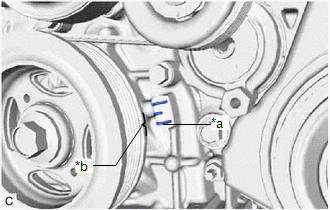
| (b) Check that the cutout of the camshaft timing gear assembly is at the top. HINT: If the cutout of the camshaft timing gear assembly is not at the top, turn the crankshaft 360° clockwise and align the timing mark (cutout) of the crankshaft pulley with the timing mark on the timing chain cover assembly again. |
|
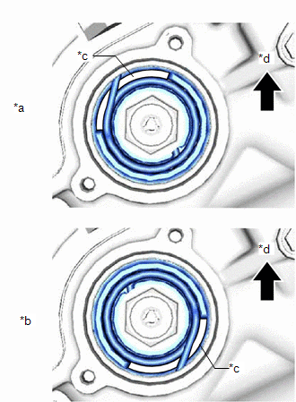
6. REMOVE CAMSHAFT TIMING GEAR BOLT
| (a) While holding the crankshaft pulley, remove the camshaft timing gear bolt. NOTICE:
|
|
READ NEXT:
 Inspection
INSPECTION PROCEDURE 1. INSPECT CAMSHAFT TIMING GEAR BOLT (a) Check the stroke of the plunger in the center of the camshaft timing gear bolt. Standard Stroke: 2.2 mm (0.0866 in.) or more HINT: Whe
Installation
INSTALLATION PROCEDURE 1. INSTALL CAMSHAFT TIMING GEAR BOLT (a) Make sure that the No. 1 cylinder is at TDC/compression. HINT: Check that the cutout of the camshaft timing gear assembly is at the top
SEE MORE:
System Diagram
SYSTEM DIAGRAM Communication Table Sender Receiver Signal Line Main Body ECU (Multiplex Network Body ECU) Sliding Roof ECU (Sliding Roof Drive Gear Assembly)
Sliding roof operation permission signal
IG signal
Front door courtesy light switch assembly signal
Vehicle speed
On-vehicle Inspection
ON-VEHICLE INSPECTION PROCEDURE 1. INSPECT STOP LIGHT SWITCH ASSEMBLY (a) Disconnect the A80 stop light switch assembly connector. *a Front view of wire harness connector (to Stop Light Switch Assembly) (b) Measure the voltage and resistance on the wire harness side connec
