Lexus ES: Installation
INSTALLATION
PROCEDURE
1. INSTALL CAMSHAFT TIMING GEAR BOLT
(a) Make sure that the No. 1 cylinder is at TDC/compression.
HINT:
Check that the cutout of the camshaft timing gear assembly is at the top and align the timing mark (cutout) of the crankshaft pulley with the timing mark on the timing chain cover assembly.
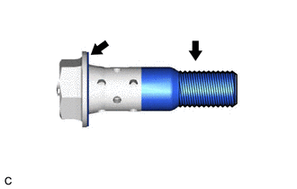
| (b) Apply engine oil to the areas of the camshaft timing gear bolt shown in the illustration. |
|
(c) While holding the crankshaft pulley, temporarily install the camshaft timing gear bolt.
Torque:
10 N·m {102 kgf·cm, 7 ft·lbf}
NOTICE:
- If the camshaft timing gear bolt has been struck or dropped, replace it.
- If there is any abnormal resistance when temporarily installing the camshaft timing gear bolt, loosen it and make sure that the No. 1 cylinder is at TDC/compression, and then temporarily install the camshaft timing gear bolt again.
HINT:
Make sure that the flange part of the camshaft timing gear bolt contacts the entire circumference of the camshaft timing gear assembly.
(d) While holding the crankshaft pulley, tighten the camshaft timing gear bolt.
Torque:
95 N·m {969 kgf·cm, 70 ft·lbf}
NOTICE:
Do not use an impact wrench.
2. INSTALL CAMSHAFT TIMING OIL CONTROL SOLENOID ASSEMBLY (for Exhaust Side of Bank 1)
Click here .gif)
3. INSPECT FOR ENGINE OIL LEAK
Click here
4. INSTALL V-BANK COVER SUB-ASSEMBLY
Click here
5. INSTALL FRONT FENDER APRON SEAL RH
Click here
6. INSTALL FRONT WHEEL RH
Click here
READ NEXT:
 Components
COMPONENTS ILLUSTRATION *1 FRONT FENDER APRON SEAL RH *2 V-BANK COVER SUB-ASSEMBLY N*m (kgf*cm, ft.*lbf): Specified torque - - ILLUSTRATION *1 CAMSHAFT TIMING GEAR BOLT
Removal
REMOVAL PROCEDURE 1. REMOVE FRONT WHEEL RH Click here 2. REMOVE FRONT FENDER APRON SEAL RH Click here 3. REMOVE V-BANK COVER SUB-ASSEMBLY Click here 4. REMOVE CAMSHAFT TIMING OIL CONTROL SOL
SEE MORE:
Installation
INSTALLATION PROCEDURE 1. INSTALL HYBRID BATTERY THERMISTOR CAUTION: Be sure to wear insulated gloves and protective goggles. (a) Engage the 3 claws of the hybrid battery thermistor (sensor portions) to install the hybrid battery thermistor to the HV battery. HINT: Install each hybrid battery the
Diagnostic Trouble Code Chart
DIAGNOSTIC TROUBLE CODE CHART Navigation System DTC No. Detection Item Link B1323 Lost Communication with Haptic Device B1324 Lost Communication with Meter B1325 Lost Communication with HUD B1326 Lost Communication with Clock Device (Local-CAN)
