Lexus ES: Removal
REMOVAL
CAUTION / NOTICE / HINT
The necessary procedures (adjustment, calibration, initialization, or registration) that must be performed after parts are removed and installed, or replaced during rear differential carrier assembly removal/installation are shown below.
Necessary Procedures After Parts Removed/Installed/Replaced| Replaced Part or Performed Procedure | Necessary Procedure | Effect/Inoperative Function when Necessary Procedure not Performed | Link |
|---|---|---|---|
| *1: for LED Type Turn Signal Light | |||
| Suspension, tires, etc. (The vehicle height changes because of suspension or tire replacement.) |
|
| |
| Rear television camera assembly optical axis adjustment (Back camera position setting) | Parking Assist Monitor System | | |
| Panoramic View Monitor System | | |
| Perform headlight ECU sub-assembly LH initialization*1 | Lighting System | | |
| Rear height control sensor sub-assembly LH | Perform headlight ECU sub-assembly LH initialization*1 | Lighting System | |
| Rear wheel alignment adjustment |
|
| |
| Exhaust system parts | Inspection after repair |
| |
CAUTION:
To prevent burns, do not touch the engine, exhaust pipe or other high temperature components while the engine is hot.
.png)
PROCEDURE
1. DRAIN DIFFERENTIAL OIL
Click here .gif)
2. REMOVE PROPELLER WITH CENTER BEARING SHAFT ASSEMBLY
Click here
3. REMOVE REAR STABILIZER BAR
Click here
4. REMOVE REAR DRIVE SHAFT ASSEMBLY LH
Click here
5. REMOVE REAR DRIVE SHAFT ASSEMBLY RH
HINT:
Use the same procedure described for the LH side.
6. REMOVE REAR DIFFERENTIAL CARRIER ASSEMBLY
(a) Disengage the 2 wire harness clamps to separate the wire harness.
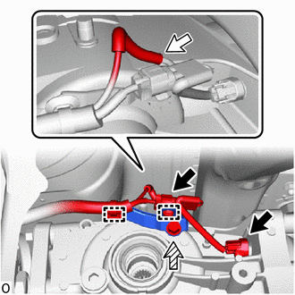
.png) | Connector |
.png) | Breather Tube |
.png) | Bolt |
(b) Disconnect the 2 connectors.
(c) Remove the bolt and wire harness clamp bracket.
(d) Remove the breather tube.
(e) Support the rear differential carrier assembly with a transmission jack.
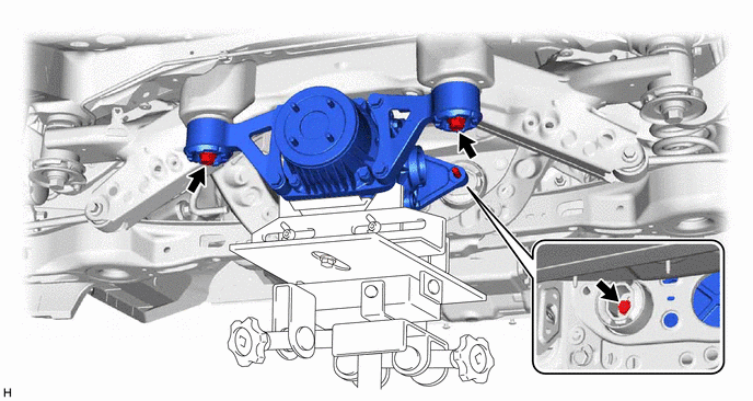
(f) Remove the 3 bolts and 2 rear lower differential mount stoppers.
(g) Slowly lower the jack and then tilt the rear differential carrier assembly.
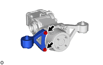
7. REMOVE REAR NO. 1 DIFFERENTIAL SUPPORT
(a) Remove the rear upper differential mount stopper from the rear No. 1 differential support.
| (b) Remove the 2 bolts and rear No. 1 differential support from the rear differential carrier assembly. |
|
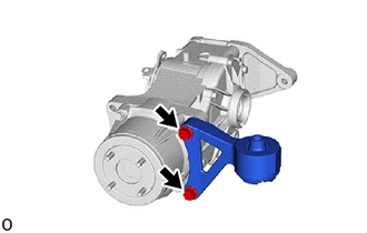
8. REMOVE REAR NO. 2 DIFFERENTIAL SUPPORT
(a) Remove the rear upper differential mount stopper from the rear No. 2 differential support.
| (b) Remove the 2 bolts and rear No. 2 differential support from the rear differential carrier assembly. |
|
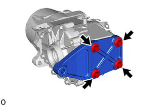
9. REMOVE REAR DIFFERENTIAL SUPPORT
| (a) Remove the 4 bolts and rear differential support from the rear differential carrier assembly. |
|
READ NEXT:
 Components
COMPONENTS ILLUSTRATION *1 REAR DIFFERENTIAL CARRIER ASSEMBLY *2 REAR NO. 1 DIFFERENTIAL SUPPORT *3 REAR NO. 2 DIFFERENTIAL SUPPORT - - Tightening torque for "Major areas in
Replacement
REPLACEMENT CAUTION / NOTICE / HINT The necessary procedures (adjustment, calibration, initialization, or registration) that must be performed after parts are removed and installed, or replaced during
SEE MORE:
Installation
INSTALLATION PROCEDURE 1. INSTALL DECK SIDE TRIM COVER RH (a) Engage the clip to install the deck side trim cover RH. 2. INSTALL LUGGAGE CLOSER MOTOR ASSEMBLY (a) Connect the connector. (b) Engage the 2 clamps. (c) Engage the 2 guides. (d) Install the luggage closer motor assembly with the 3 bolt
Power Mirrors do not Return to Memorized Position
DESCRIPTION If any of the M1, M2 or M3 seat memory switch is pressed, the outer mirror control ECU assembly (driver door) detects the switch operation and sends the seat memory switch signal to the main body ECU (multiplex network body ECU) via CAN communication. The main body ECU (multiplex network
