Lexus ES: Replacement
REPLACEMENT
CAUTION / NOTICE / HINT
The necessary procedures (adjustment, calibration, initialization, or registration) that must be performed after parts are removed and installed, or replaced during diaphragm oil seal removal/installation are shown below.
Necessary Procedures After Parts Removed/Installed/Replaced| Replaced Part or Performed Procedure | Necessary Procedure | Effect/Inoperative Function when Necessary Procedure not Performed | Link |
|---|---|---|---|
| *1: for LED Type Turn Signal Light | |||
| Rear wheel alignment adjustment |
|
| |
| Suspension, tires, etc. (The vehicle height changes because of suspension or tire replacement) |
|
| |
| Rear television camera assembly optical axis adjustment (Back camera position setting) | Parking Assist Monitor System | | |
| Panoramic View Monitor System | | |
| Perform headlight ECU sub-assembly LH initialization*1 | Lighting System | | |
| Rear height control sensor sub-assembly LH | Perform headlight ECU sub-assembly LH initialization*1 | Lighting System | |
| Exhaust system parts | Inspection after repair |
| |
CAUTION:
To prevent burns, do not touch the engine, exhaust pipe or other high temperature components while the engine is hot.
.png)
PROCEDURE
1. REMOVE REAR DIFFERENTIAL CARRIER ASSEMBLY
Click here .gif)
2. REMOVE REAR NO. 1 DIFFERENTIAL SUPPORT
Click here
3. REMOVE REAR NO. 2 DIFFERENTIAL SUPPORT
Click here
4. REMOVE TRANSMISSION COUPLING ASSEMBLY
Click here
5. REMOVE TRANSMISSION COUPLING CONICAL SPRING WASHER
Click here
6. REMOVE TRANSMISSION COUPLING SHIM
Click here
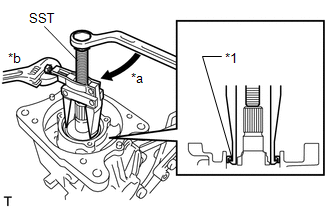
7. REMOVE DIAPHRAGM OIL SEAL
| (a) Using SST, remove the diaphragm oil seal from the rear differential carrier sub-assembly. SST: 09308-10010 |
|
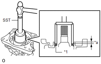
8. INSTALL DIAPHRAGM OIL SEAL
(a) Coat the lip of a new diaphragm oil seal with MP grease.
| (b) Using SST and a hammer, tap the diaphragm oil seal into the rear differential carrier sub-assembly until it reaches the standard value. SST: 09710-30021 09710-03121 SST: 09950-60011 09951-00570 SST: 09950-70010 09951-07100 Standard distance: 6.5 to 7.5 mm (0.256 to 0.295 in.) (from the edge of the differential carrier sub-assembly) NOTICE:
|
|
9. INSTALL TRANSMISSION COUPLING SHIM
Click here
10. INSTALL TRANSMISSION COUPLING CONICAL SPRING WASHER
Click here
11. INSTALL TRANSMISSION COUPLING ASSEMBLY
Click here
12. INSTALL REAR NO. 1 DIFFERENTIAL SUPPORT
Click here
13. INSTALL REAR NO. 2 DIFFERENTIAL SUPPORT
Click here
14. INSTALL REAR DIFFERENTIAL CARRIER ASSEMBLY
Click here
READ NEXT:
 Components
COMPONENTS ILLUSTRATION *1 REAR DRIVE SHAFT OIL SEAL LH - - ● Non-reusable part MP grease
Replacement
REPLACEMENT CAUTION / NOTICE / HINT The necessary procedures (adjustment, calibration, initialization, or registration) that must be performed after parts are removed and installed, or replaced during
SEE MORE:
Cruise Control Input Processor (P160700)
DESCRIPTION When the ECM detects that it is not functioning normally, DTC P160700 is stored. DTC No. Detection Item DTC Detection Condition Trouble Area MIL DTC Output from P160700 Cruise Control Input Processor When the engine switch is on (IG) and control of vehicle speed by t
Freeze Frame Data
FREEZE FRAME DATA FREEZE FRAME DATA NOTICE:
Freeze frame data values will vary depending on the measurement conditions, surroundings, or vehicle conditions. For this reason, there may be a problem even when the values are within specifications.
Turn the power switch on (IG) and park the vehicle
