Lexus ES: Inspection
INSPECTION
PROCEDURE
1. INSPECT VACUUM SWITCHING VALVE (for Active Control Engine Mount System)
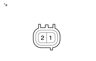
(a) Measure the resistance.
| (1) Measure the resistance according to the value(s) in the table below. Standard Resistance:
If the result is not as specified, replace the vacuum switching valve (for active control engine mount system). |
|
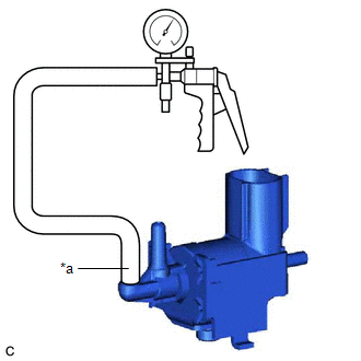
(b) Check the operation of the vacuum switching valve (for active control engine mount system).
| (1) Using a vacuum pump, apply a vacuum of 67 kPa (503 mmHg, 19.8 in. Hg) to port (F) and check that the vacuum is maintained. OK: Vacuum pressure holds. If the result is not as specified, replace the vacuum switching valve (for active control engine mount system). |
|
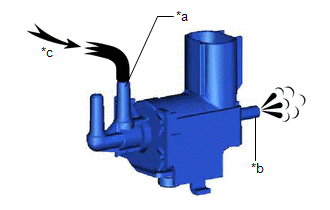
| (2) Check that air flows from port (E) to port (G). Standard: Air flows from port (E) to port (G). If the result is not as specified, replace the vacuum switching valve (for active control engine mount system). |
|
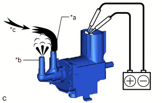
| (3) Apply battery voltage to the terminals and check that air flows from port (E) to port (F). Standard: Air flows from port (E) to port (F). If the result is not as specified, replace the vacuum switching valve (for active control engine mount system). |
|
READ NEXT:
 Installation
INSTALLATION PROCEDURE 1. INSTALL VACUUM SWITCHING VALVE (for Active Control Engine Mount System) (a) Install the vacuum switching valve (for active control engine mount system) to the front engine mo
SEE MORE:
Freeze Frame Data
FREEZE FRAME DATA FREEZE FRAME DATA NOTICE:
Freeze frame data values will vary depending on the measurement conditions, surroundings, or vehicle conditions. For this reason, there may be a problem even when the values are within specifications.
Turn the power switch on (IG) and park the vehicle
Components
COMPONENTS ILLUSTRATION *1 FUEL DELIVERY PIPE RH *2 FUEL DELIVERY PIPE WITH SENSOR ASSEMBLY LH *3 DIRECT FUEL INJECTOR ASSEMBLY *4 FUEL INJECTOR SEAL *5 NO. 2 FUEL PIPE SUB-ASSEMBLY *6 WIRE HARNESS CLAMP BRACKET *7 NO. 3 FUEL INJECTOR BACK-UP RING *8 O-RING
