Lexus ES: Removal
REMOVAL
CAUTION / NOTICE / HINT
The necessary procedures (adjustment, calibration, initialization or registration) that must be performed after parts are removed and installed, or replaced during auxiliary battery removal/installation are shown below.
Necessary Procedures After Parts Removed/Installed/Replaced|
Replaced Part or Performed Procedure |
Necessary Procedure |
Effect/Inoperative Function when Necessary Procedure not Performed |
Link |
|---|---|---|---|
| *1: When performing learning using the Techstream.
Click here |
|||
|
Auxiliary battery terminal is disconnected/reconnected |
Perform steering sensor zero point calibration |
Lane Control System |
|
|
Pre-collision System |
|||
|
Parking Support Brake System* |
|||
|
Lighting System |
|||
|
Memorize steering angle neutral point |
Parking assist monitor system |
|
|
|
Panoramic view monitor system |
|
||
|
Initialize power trunk lid system |
Power Trunk Lid System |
|
|
.gif)
NOTICE:
- After the power switch is turned off, the radio receiver assembly records various types of memory and settings. As a result, after turning the power switch off, make sure to wait at least 85 seconds before disconnecting the cable from the negative (-) auxiliary battery terminal. (for Audio and Visual System)
- After the power switch is turned off, the radio receiver assembly records various types of memory and settings. As a result, after turning the power switch off, make sure to wait at least 85 seconds before disconnecting the cable from the negative (-) auxiliary battery terminal. (for Navigation System)
- When replacing the auxiliary battery, use a new auxiliary battery of the same dimensions and same capacity or more from the same class at a 20-hour rate.
- After replacing the auxiliary battery, install the ventilation hole plug supplied with the new auxiliary battery or the ventilation hole plug from the old auxiliary battery to the ventilation hole on the side to which the battery hose is not connected.
PROCEDURE
1. DISCONNECT CABLE FROM NEGATIVE AUXILIARY BATTERY TERMINAL
(a) Turn back the luggage compartment trim cover RH as shown in the illustration.
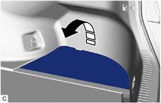
.png) |
Remove in this Direction |
|
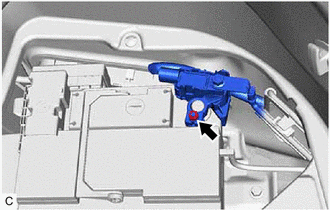
(b) Loosen the nut, and disconnect the cable from the negative (-) auxiliary battery terminal. NOTICE: When disconnecting the cable, some systems need to be initialized after the cable is reconnected. Click here |
|
2. REMOVE AUXILIARY BATTERY
(a) Disengage the 2 claws and open the battery terminal connector cover in the order shown in the illustration.
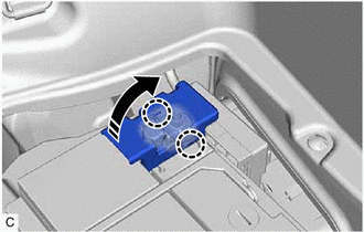
|
|
Remove in this Direction |
|
(b) Loosen the nut and disconnect the cable from the positive (+) auxiliary battery terminal. |
|
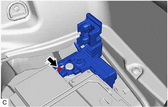
|
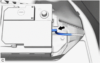
(c) Disconnect the battery hose from the auxiliary battery. |
|
(d) Remove the bolt and remove the No. 3 battery clamp as shown in the illustration.
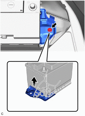
|
|
Remove in this Direction |
(e) Remove the auxiliary battery.
READ NEXT:
 Installation
INSTALLATION
PROCEDURE
1. INSTALL AUXILIARY BATTERY
(a) Install the auxiliary battery.
(b) Install the No. 3 battery clamp with the bolt.
Install in this Direction
Components
COMPONENTS
ILLUSTRATION
*1
RADIATOR CAP SUB-ASSEMBLY
*2
RADIATOR DRAIN COCK PLUG
*3
NO. 1 ENGINE UNDER COVER
-
SEE MORE:
Dtc Check / Clear
DTC CHECK / CLEAR CHECK DTC (a) Turn the engine switch off. (b) Connect the Techstream to the DLC3. (c) Turn the engine switch on (IG). (d) Turn the Techstream on. (e) Enter the following menus: Body Electrical / Tilt & Telescopic / Trouble Codes. Body Electrical > Tilt&Telescopic > Tr
Terminals Of Ecu
TERMINALS OF ECU CHECK SLIDING ROOF ECU (SLIDING ROOF DRIVE GEAR SUB-ASSEMBLY) (a) Disconnect the P22 sliding roof ECU (sliding roof drive gear sub-assembly) connector. (b) Measure the resistance and voltage according to the value(s) in the table below. HINT: Measure the values on the wire harness
