Lexus ES: Removal
REMOVAL
PROCEDURE
1. REMOVE THROTTLE BODY WITH MOTOR ASSEMBLY
Click here .gif)
2. REMOVE NO. 2 SURGE TANK STAY
Click here
3. SEPARATE ENGINE WIRE
| (a) Remove the 2 bolts and separate the engine wire. |
|
.png)
| (b) Remove the bolt and separate the earth wire. |
|
.png)
4. DISCONNECT AIR TUBE
| (a) Slide the clip and disconnect the air tube from the vacuum pump assembly. |
|
.png)
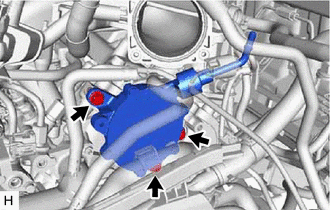
5. REMOVE VACUUM PUMP ASSEMBLY
| (a) Remove the 3 bolts and vacuum pump assembly from the engine assembly. |
|
| (b) Remove the No. 2 O-ring and No. 3 O-ring from the vacuum pump assembly. |
|
.png)
READ NEXT:
 Components
COMPONENTS ILLUSTRATION *1 ENGINE WIRE *2 NO. 2 SURGE TANK STAY *3 EARTH WIRE - - Tightening torque for "Major areas involving basic vehicle performance such as moving/turni
Installation
INSTALLATION CAUTION / NOTICE / HINT HINT: Refer to the illustration to confirm the type of vacuum pump assembly. *A for Type A *B for Type B *a Label - - PROCEDURE 1. INSTALL V
SEE MORE:
Fuel Lid Opener does not Operate
DESCRIPTION When the trunk and fuel switch assembly (fuel lid opener switch) is pushed, a trunk and fuel switch assembly (fuel lid opener switch) signal is sent to the ECM. The ECM turns on the FUEL OPN relay and EFI-MAIN NO. 1 relay, and the fuel lid lock with motor assembly opens the fuel lid. Whe
Parts Location
PARTS LOCATION ILLUSTRATION *1 CANISTER (CHARCOAL CANISTER ASSEMBLY) *2 EGR VALVE ASSEMBLY *3 FUEL TANK CAP ASSEMBLY *4 FUEL VAPOR CONTAINMENT VALVE (FUEL TANK SOLENOID MAIN VALVE ASSEMBLY) *5 PCV VALVE (VENTILATION VALVE SUB-ASSEMBLY) *6 PURGE VALVE (PURGE VSV) *7
© 2016-2026 Copyright www.lexguide.net
