Lexus ES: Components
Lexus ES (XZ10) Service Manual / Brake / Brake System (other) / Vacuum Pump(for Tmmk Made) / Components
COMPONENTS
ILLUSTRATION
.png)
| *1 | ENGINE WIRE | *2 | NO. 2 SURGE TANK STAY |
| *3 | EARTH WIRE | - | - |
.png) | Tightening torque for "Major areas involving basic vehicle performance such as moving/turning/stopping": N*m (kgf*cm, ft.*lbf) | .png) | N*m (kgf*cm, ft.*lbf): Specified torque |
ILLUSTRATION
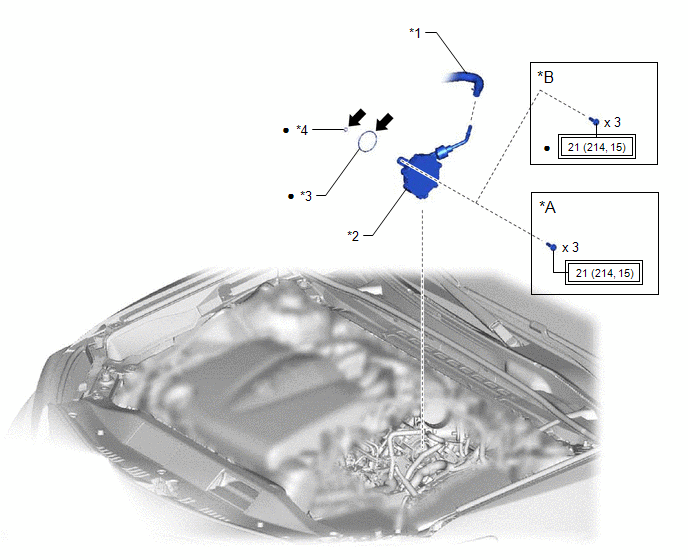
| *A | for Type A | *B | for Type B |
| *1 | AIR TUBE | *2 | VACUUM PUMP ASSEMBLY |
| *3 | NO. 2 O-RING | *4 | NO. 3 O-RING |
| | Tightening torque for "Major areas involving basic vehicle performance such as moving/turning/stopping": N*m (kgf*cm, ft.*lbf) | ● | Non-reusable part |
.png) | Engine oil | - | - |
READ NEXT:
 Installation
INSTALLATION CAUTION / NOTICE / HINT HINT: Refer to the illustration to confirm the type of vacuum pump assembly. *A for Type A *B for Type B *a Label - - PROCEDURE 1. INSTALL V
On-vehicle Inspection
ON-VEHICLE INSPECTION PROCEDURE 1. REMOVE COWL TOP VENTILATOR LOUVER SUB-ASSEMBLY Click here 2. REMOVE FRONT CENTER UPPER SUSPENSION BRACE SUB-ASSEMBLY Click here 3. OPERATION CHECK (a) Slide th
Removal
REMOVAL CAUTION / NOTICE / HINT HINT: Refer to the illustration to confirm the type of vacuum pump assembly. *A for Type A *B for Type B *a Label - - PROCEDURE 1. REMOVE THROTTL
SEE MORE:
System Diagram
SYSTEM DIAGRAM Communication Table Transmitting ECU (Transmitter) Receiving ECU Signal Communication Method Main Body ECU (Multiplex Network Body ECU) Multiplex Tilt and Telescopic ECU
IG SW signal
Store command of driver seat memory
Recall command of driver seat memory
A
Control Module Communication Bus Off (U0073,U0100,U0101,U0126,U0129,U0142,U0155,U0242)
DESCRIPTION These DTCs are stored if a CAN communication malfunction occurs between the headlight ECU sub-assembly LH and other ECUs. for LED Type Turn Signal Light DTC No. Detection Item DTC Detection Condition Trouble Area DTC Output from U0073 Control Module Communication Bus Off
© 2016-2026 Copyright www.lexguide.net
