Lexus ES: Installation
INSTALLATION
CAUTION / NOTICE / HINT
HINT:
Refer to the illustration to confirm the type of vacuum pump assembly.
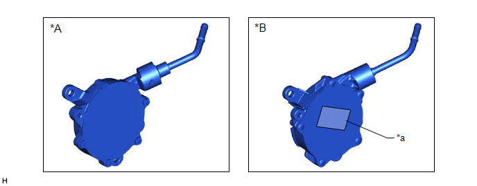
| *A | for Type A | *B | for Type B |
| *a | Label | - | - |
PROCEDURE
1. INSTALL VACUUM PUMP ASSEMBLY
(a) When using a new vacuum pump assembly:
(1) Apply engine oil to the No. 2 O-ring and No. 3 O-ring which are installed to a new vacuum pump assembly.
.png)
| *1 | No. 2 O-ring |
| *2 | No. 3 O-ring |
.png) | Engine oil |
(b) When reusing the vacuum pump assembly:
(1) Apply engine oil to a new No. 2 O-ring and No. 3 O-ring and install them to the vacuum pump assembly.
| *1 | No. 2 O-ring |
| *2 | No. 3 O-ring |
| | Engine oil |
(c) Apply engine oil to the inner surface of the installation hole.
| (d) Temporarily install the vacuum pump assembly so that the oil pipe engages with the hole of the camshaft and the coupling teeth engage with the groove of the camshaft. NOTICE:
|
|
.png)
(e) for Type A:
| (1) Install the vacuum pump assembly with the 3 bolts. Torque: 21 N·m {214 kgf·cm, 15 ft·lbf} NOTICE:
|
|
.png)
(f) for Type B:
| (1) Install the vacuum pump assembly with 3 new bolts. Torque: 21 N·m {214 kgf·cm, 15 ft·lbf} NOTICE:
|
|
2. CONNECT AIR TUBE
| (a) Connect the air tube to the vacuum pump assembly and slide the clip to secure it. |
|
.png)
3. INSTALL ENGINE WIRE
| (a) Install the earth wire with the bolt. Torque: 10 N·m {102 kgf·cm, 7 ft·lbf} |
|
.png)
| (b) Install the engine wire with the 2 bolts. Torque: 10 N·m {102 kgf·cm, 7 ft·lbf} |
|
.png)
4. INSTALL NO. 2 SURGE TANK STAY
| (a) Install the No. 2 surge tank stay with the 2 bolts in the order shown in the illustration. Torque: 21 N·m {214 kgf·cm, 15 ft·lbf} |
|
.png)
5. INSTALL THROTTLE BODY WITH MOTOR ASSEMBLY
Click here .gif)
6. INSPECT VACUUM PUMP OPERATION
Click here
READ NEXT:
 On-vehicle Inspection
ON-VEHICLE INSPECTION PROCEDURE 1. REMOVE COWL TOP VENTILATOR LOUVER SUB-ASSEMBLY Click here 2. REMOVE FRONT CENTER UPPER SUSPENSION BRACE SUB-ASSEMBLY Click here 3. OPERATION CHECK (a) Slide th
Removal
REMOVAL CAUTION / NOTICE / HINT HINT: Refer to the illustration to confirm the type of vacuum pump assembly. *A for Type A *B for Type B *a Label - - PROCEDURE 1. REMOVE THROTTL
SEE MORE:
System Description
SYSTEM DESCRIPTION GENERAL (a) The parking support alert system has a static objects function, rear crossing vehicles function, and rear pedestrians.
Parking Support Alert (static objects) function
This system uses ultrasonic sensors to detect any obstacles at the corners and the rear of the v
Kick Sensor Circuit (B2205)
DESCRIPTION DTC B2205 is output when the luggage closer motor assembly detects that the kick door control sensor is stuck on. DTC No. Detection Item DTC Detection Condition Trouble Area B2205 Kick Sensor Circuit One of the following conditions is met for approximately 60 seconds or
