Lexus ES: Power Mirror Surface Position is not Memorized
DESCRIPTION
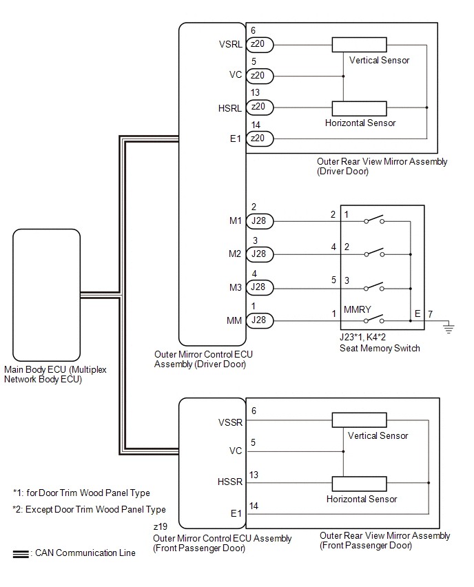
If any of the M1, M2 or M3 seat memory switch is pressed, the outer mirror control ECU assembly (driver door) detects the switch operation and sends the seat memory switch signal to the main body ECU (multiplex network body ECU) via CAN communication. On receiving the seat memory switch signal, the main body ECU (multiplex network body ECU) sends the memory request signal to each outer mirror control ECU assembly via CAN communication. When receiving this signal, each outer mirror control ECU assembly stores the mirror surface position based on information from the mirror position sensor, which is built into the outer rear view mirror assembly.
WIRING DIAGRAM
CAUTION / NOTICE / HINT
NOTICE:
-
The power mirror control system (w/ Memory) uses the CAN communication system. Inspect the communication functions by following How to Proceed with Troubleshooting. Troubleshoot the power mirror control system (w/ Memory) after confirming that the communication systems are functioning properly.
Click here
.gif)
-
Before replacing the main body ECU (multiplex network body ECU), refer to Registration.
Click here
- The mirror surface position will not be memorized if the power switch is not on (IG).
- The mirror surface position will not be stored if the seat memory SET switch and 2 or more seat memory switches are pressed simultaneously.
- If the operation fails, the mirror surface position will not be memorized until the seat memory SET switch is released and the operation is attempted again.
- The mirror surface position will not be memorized when the mirror is operated manually.
HINT:
Each outer rear view mirror assembly has a built-in mirror vertical position sensor and mirror horizontal position sensor.
PROCEDURE
| 1. | READ VALUE USING TECHSTREAM |
(a) Connect the Techstream to the DLC3.
(b) Turn the power switch on (IG).
(c) Turn the Techstream on.
(d) Enter the following menus: Body Electrical / Mirror L or Mirror R / Data List.
(e) Read the Data List according to the display on the Techstream.
Body Electrical > Mirror L > Data List| Tester Display | Measurement Item | Range | Normal Condition | Diagnostic Note |
|---|---|---|---|---|
| Seat Memory Switch1 | Seat memory switch M1 switch signal | OFF or ON | OFF: Seat memory switch M1 switch off ON: Seat memory switch M1 switch on | - |
| Seat Memory Switch2 | Seat memory switch M2 switch signal | OFF or ON | OFF: Seat memory switch M2 switch off ON: Seat memory switch M2 switch on | - |
| Seat Memory Switch3 | Seat memory switch M3 switch signal | OFF or ON | OFF: Seat memory switch M3 switch off ON: Seat memory switch M3 switch on | - |
| Seat Memory Set SW | Seat memory switch SET switch signal | OFF or ON | OFF: Seat memory switch SET switch off ON: Seat memory switch SET switch on | - |
| Tester Display |
|---|
| Seat Memory Switch1 |
| Seat Memory Switch2 |
| Seat Memory Switch3 |
| Seat Memory Set SW |
| Tester Display | Measurement Item | Range | Normal Condition | Diagnostic Note |
|---|---|---|---|---|
| Seat Memory Switch1 | Seat memory switch M1 switch signal | OFF or ON | OFF: Seat memory switch M1 switch off ON: Seat memory switch M1 switch on | - |
| Seat Memory Switch2 | Seat memory switch M2 switch signal | OFF or ON | OFF: Seat memory switch M2 switch off ON: Seat memory switch M2 switch on | - |
| Seat Memory Switch3 | Seat memory switch M3 switch signal | OFF or ON | OFF: Seat memory switch M3 switch off ON: Seat memory switch M3 switch on | - |
| Seat Memory Set SW | Seat memory switch SET switch signal | OFF or ON | OFF: Seat memory switch SET switch off ON: Seat memory switch SET switch on | - |
| Tester Display |
|---|
| Seat Memory Switch1 |
| Seat Memory Switch2 |
| Seat Memory Switch3 |
| Seat Memory Set SW |
OK:
On the Techstream screen, ON or OFF is displayed accordingly.
| NG | .gif) | GO TO STEP 8 |
|
.gif)
| 2. | CHECK SEAT MEMORY SWITCH (SEAT POSITION MEMORY FUNCTION) |
(a) When any seat memory switch (M1, M2 or M3) is pressed, check that the driver seat moves to the memorized position.
Click here
OK:
The driver seat moves to the memorized position.
| NG | | GO TO FRONT POWER SEAT CONTROL SYSTEM (Power Seat does not Return to Memorized Position) |
|
| 3. | CHECK MEMORY AND REACTIVATION FUNCTION |
| (a) Turn the power switch on (IG). |
|
(b) Using the outer mirror switch assembly, turn the mirror surface to the fully left position.
(c) Press the M1 switch while the SET switch is being pressed.
(d) Check that the buzzer sounds for 0.5 seconds and the mirror surface position is memorized.
(e) Using the outer mirror switch assembly, turn the mirror surface to the fully right position.
(f) Press the M1 switch.
(g) Check that the buzzer sounds for 0.1 seconds and the outer mirror automatically moves to the memorized fully left position.
| Result | Proceed to |
|---|---|
| Memory and reactivation functions on both mirrors are not normal | A |
| Memory and reactivation functions on driver door mirror are not normal | B |
| Memory and reactivation functions on front passenger door mirror are not normal | C |
| A | | REPLACE MAIN BODY ECU (MULTIPLEX NETWORK BODY ECU) |
| C | | GO TO STEP 6 |
|
| 4. | REPLACE OUTER REAR VIEW MIRROR ASSEMBLY (DRIVER DOOR) |
(a) Temporarily replace the outer rear view mirror assembly (driver door) with a new or known good one.
Click here
|
| 5. | CHECK MEMORY AND REACTIVATION FUNCTION |
| (a) Turn the power switch on (IG). |
|
(b) Using the outer mirror switch assembly, turn the mirror surface to the fully left position.
(c) Press the M1 switch while the SET switch is being pressed.
(d) Check that the buzzer sounds for 0.5 seconds and the mirror surface position is memorized.
(e) Using the outer mirror switch assembly, turn the mirror surface to the fully right position.
(f) Press the M1 switch.
(g) Check that the buzzer sounds for 0.1 seconds and the outer mirror automatically moves to the memorized fully left position.
| OK | | END (OUTER REAR VIEW MIRROR ASSEMBLY (DRIVER DOOR) WAS DEFECTIVE) |
| NG | | REPLACE OUTER MIRROR CONTROL ECU ASSEMBLY (DRIVER DOOR) |
| 6. | REPLACE OUTER REAR VIEW MIRROR ASSEMBLY (FRONT PASSENGER DOOR) |
(a) Temporarily replace the outer rear view mirror assembly (front passenger door) with a new or known good one.
Click here
|
| 7. | CHECK MEMORY AND REACTIVATION FUNCTION |
| (a) Turn the power switch on (IG). |
|
(b) Using the outer mirror switch assembly, turn the mirror surface to the fully left position.
(c) Press the M1 switch while the SET switch is being pressed.
(d) Check that the buzzer sounds for 0.5 seconds and the mirror surface position is memorized.
(e) Using the outer mirror switch assembly, turn the mirror surface to the fully right position.
(f) Press the M1 switch.
(g) Check that the buzzer sounds for 0.1 seconds and the outer mirror automatically moves to the memorized fully left position.
| OK | | END (OUTER REAR VIEW MIRROR ASSEMBLY (FRONT PASSENGER DOOR) WAS DEFECTIVE) |
| NG | | REPLACE OUTER MIRROR CONTROL ECU ASSEMBLY (FRONT PASSENGER DOOR) |
| 8. | INSPECT SEAT MEMORY SWITCH |
(a) Remove the seat memory switch.
Click here
(b) Inspect the seat memory switch.
Click here
| NG | | REPLACE SEAT MEMORY SWITCH |
|
| 9. | CHECK HARNESS AND CONNECTOR (SEAT MEMORY SWITCH - OUTER MIRROR CONTROL ECU ASSEMBLY (DRIVER DOOR) - BODY GROUND) |
(a) Disconnect the J28 outer mirror control ECU assembly (driver door) connector.
(b) Disconnect the J23*1 or K4*2 seat memory switch connector.
- *1: for Door Trim Wood Panel Type
- *2: except Door Trim Wood Panel Type
(c) Measure the resistance according to the value(s) in the table below.
Standard Resistance:
for Door Trim Wood Panel Type| Tester Connection | Condition | Specified Condition |
|---|---|---|
| J28-1 (MM) - J23-1 (MMRY) | Always | Below 1 Ω |
| J28-2 (M1) - J23-2 (1) | Always | Below 1 Ω |
| J28-3 (M2) - J23-4 (2) | Always | Below 1 Ω |
| J28-4 (M3) - J23-5 (3) | Always | Below 1 Ω |
| J23-7 (E) - Body ground | Always | Below 1 Ω |
| J28-1 (MM) or J23-1 (MMRY) - Body ground | Always | 10 kΩ or higher |
| J28-2 (M1) or J23-2 (1) - Body ground | Always | 10 kΩ or higher |
| J28-3 (M2) or J23-4 (2) - Body ground | Always | 10 kΩ or higher |
| J28-4 (M3) or J23-5 (3) - Body ground | Always | 10 kΩ or higher |
| Tester Connection | Condition | Specified Condition |
|---|---|---|
| J28-1 (MM) - K4-1 (MMRY) | Always | Below 1 Ω |
| J28-2 (M1) - K4-2 (1) | Always | Below 1 Ω |
| J28-3 (M2) - K4-4 (2) | Always | Below 1 Ω |
| J28-4 (M3) - K4-5 (3) | Always | Below 1 Ω |
| K4-7 (E) - Body ground | Always | Below 1 Ω |
| J28-1 (MM) or K4-1 (MMRY) - Body ground | Always | 10 kΩ or higher |
| J28-2 (M1) or K4-2 (1) - Body ground | Always | 10 kΩ or higher |
| J28-3 (M2) or K4-4 (2) - Body ground | Always | 10 kΩ or higher |
| J28-4 (M3) or K4-5 (3) - Body ground | Always | 10 kΩ or higher |
| OK | | REPLACE OUTER MIRROR CONTROL ECU ASSEMBLY (DRIVER DOOR) |
| NG | | REPAIR OR REPLACE HARNESS OR CONNECTOR |
READ NEXT:
 Power Mirrors do not Return to Memorized Position
DESCRIPTION If any of the M1, M2 or M3 seat memory switch is pressed, the outer mirror control ECU assembly (driver door) detects the switch operation and sends the seat memory switch signal to the ma
Reverse Shift-linked Function of Power Mirrors does not Operate
DESCRIPTION The ECM sends the reverse signal to the main body ECU (multiplex network body ECU) via CAN communication. When receiving the reverse signal, the main body ECU (multiplex network body ECU)
SEE MORE:
Light Sensor Circuit (B1244)
DESCRIPTION The automatic light control sensor detects ambient light. The sensor creates an electrical signal based on the amount of light detected, and sends the signal to the main body ECU (multiplex network body ECU). The main body ECU (multiplex network body ECU) turns on or off the headlights a
Throttle Actuator "A" Control Motor Circuit Current Below Threshold (P210018,P210019)
DESCRIPTION The throttle actuator is operated by the ECM and opens and closes the throttle valve using gears. The opening angle of the throttle valve is detected by the throttle position sensor, which is mounted on the throttle body with motor assembly. The throttle position sensor provides feedback
