Lexus ES: Reverse Shift-linked Function of Power Mirrors does not Operate
DESCRIPTION
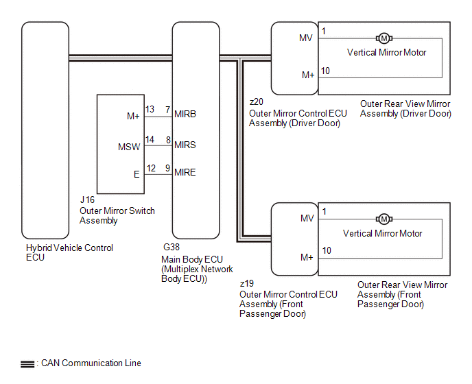
The ECM sends the reverse signal to the main body ECU (multiplex network body ECU) via CAN communication. When receiving the reverse signal, the main body ECU (multiplex network body ECU) sends the reverse request signal to each outer mirror control ECU assembly. Based on the signal, each outer mirror control ECU assembly then performs control.
WIRING DIAGRAM
CAUTION / NOTICE / HINT
NOTICE:
-
The power mirror control system (w/ Memory) uses the CAN communication system. Inspect the communication functions by following How to Proceed with Troubleshooting. Troubleshoot the power mirror control system (w/ Memory) after confirming that the communication systems are functioning properly.
Click here
.gif)
-
Before replacing the main body ECU (multiplex network body ECU), refer to Registration.
Click here
PROCEDURE
| 1. | CHECK ELECTRICAL REMOTE CONTROL MIRROR FUNCTION |
(a) Check the electrical remote control mirror function operates normally.
Click here
OK:
Power electrical remote control mirror function operates normally.
| Result | Proceed to |
|---|---|
| Electrical remote control mirror function is normal | A |
| Driver door electrical remote control mirror function is not normal | B |
| Front passenger door electrical remote control mirror function is not normal | C |
| B | .gif) | GO TO OTHER DIAGNOSTIC PROCEDURE (Driver Side Power Mirror cannot be Adjusted with Power Mirror Switch) |
| C | | GO TO OTHER DIAGNOSTIC PROCEDURE (Front Passenger Side Power Mirror cannot be Adjusted with Power Mirror Switch) |
|
.gif)
| 2. | CHECK MEMORY AND REACTIVATION FUNCTION |
| (a) Turn the power switch on (IG). |
|
(b) Using the outer mirror switch assembly, turn the mirror surface to the fully left position.
(c) Press the M1 switch while the SET switch is being pressed.
(d) Check that the buzzer sounds for 0.5 seconds and the mirror surface position is memorized.
(e) Using the outer mirror switch assembly, turn the mirror surface to the fully right position.
(f) Press the M1 switch.
(g) Check that the buzzer sounds for 0.1 seconds and the outer mirror automatically moves to the memorized fully left position.
| Result | Proceed to |
|---|---|
| Memory and reactivation functions are normal | A |
| Memory function is not normal | B |
| Reactivation function is not normal | C |
| B | | GO TO OTHER DIAGNOSTIC PROCEDURE (Power Mirror Surface Position is not Memorized) |
| C | | GO TO OTHER DIAGNOSTIC PROCEDURE (Power Mirrors do not Return to Memorized Position) |
|
| 3. | CHECK FOR DTC |
(a) Connect the Techstream to the DLC3.
(b) Turn the power switch on (IG).
(c) Turn the Techstream on.
(d) Enter the following menus: Powertrain / Engine / DTC.
(e) Check if SFI system DTCs are output.
Powertrain > Engine > Trouble CodesOK:
SFI system DTCs are not output.
| NG | | GO TO SFI SYSTEM |
|
| 4. | CHECK COMBINATION METER ASSEMBLY |
(a) Check if the shift position indicator light in the combination meter assembly operates normally.
OK:
Shift position indicator light indicates the actual shift position correctly.
| NG | | GO TO METER / GAUGE SYSTEM |
|
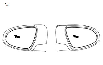
| 5. | CHECK REVERSE SHIFT-LINKED FUNCTION |
| (a) Turn the power switch on (IG). |
|
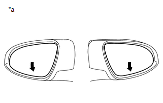
(b) Turn the mirror select switch R or L switch on.
(c) Check that the mirror surface turns downward when the shift lever is moved to R.
| Result | Proceed to |
|---|---|
| Reverse shift-linked functions on both mirrors are not normal | A |
| Reverse shift-linked function on driver door is not normal | B |
| Reverse shift-linked function on front passenger door is not normal | C |
| A | | REPLACE MAIN BODY ECU (MULTIPLEX NETWORK BODY ECU) |
| B | | REPLACE OUTER MIRROR CONTROL ECU ASSEMBLY (DRIVER DOOR) |
| C | | REPLACE OUTER MIRROR CONTROL ECU ASSEMBLY (FRONT PASSENGER DOOR) |
READ NEXT:
 Precaution
PRECAUTION PRECAUTION FOR DISCONNECTING CABLE FROM NEGATIVE AUXILIARY BATTERY TERMINAL NOTICE: When disconnecting the cable from the negative (-) auxiliary battery terminal, initialize the following s
Parts Location
PARTS LOCATION ILLUSTRATION *1 OUTER MIRROR SWITCH ASSEMBLY *2 OUTER REAR VIEW MIRROR ASSEMBLY LH *3 OUTER REAR VIEW MIRROR ASSEMBLY RH *4 DEF RELAY *5 OUTER MIRROR LH *6
SEE MORE:
Software Incompatibility with Cruise Control Module Invalid/Incompatible Software Component (U030557)
DESCRIPTION The millimeter wave radar sensor assembly receives vehicle information from the forward recognition camera via CAN communication. If the vehicle information stored in the forward recognition camera differs from that stored in the millimeter wave radar sensor assembly, the millimeter wave
Removal
REMOVAL CAUTION / NOTICE / HINT The necessary procedures (adjustment, calibration, initialization or registration) that must be performed after parts are removed and installed, or replaced during steering column assembly removal/installation are shown below. Necessary Procedures After Parts Removed/
